Theory
A vector network analyzer is a device that measures scattering parameters.
The scattering parameters, or S-parameters. For a network with two ports (e.g., an attenuator), the S parameter consists of four components, denoted by Sij , where i denotes the port to be detected and j denotes the incident port of the excitation signal.
S11 : The reflection of the signal from a port of the device under test (DUT), also known as return loss;
S21 : the change in the signal as it passes through the device under test (amplitude and phase change, also known as insertion loss or gain);
S12 : the change produced when the signal passes through the device under test in the opposite direction;
S22 : The reflection of the other port of the device under test to the signal entering from that port.
From the above definition, it can be seen that the scattering parameters can be measured by understanding the changes produced by the signal flowing through the device under test and reflected by the device. The network analyzer will generate an excitation signal by itself, let the excitation signal send into the device under test, and at the same time use multiple receivers to measure the characteristics of the excitation signal before and after entering the device under test respectively, compare them, and get the S-parameter by calculation.
The diagram at the top of the next page shows the RF block diagram of the KC901. Taking S11 and S21 of the measurement two-port device as an example, the path of the excitation signal is shown in red. After being generated by the frequency source, it is conditioned by the step attenuator and bypassable amplifier, and the forward reference signal R1 and reverse signal A are extracted through the forward and reverse couplers, outputted to the device under test (DUT) through port 1, outputted from the other port of the DUT, arriving at port 2, and extracted through the reverse coupler of port 2 to get Transmission signal B. The three signals R1, A and B are transformed to the same IF frequency by three identical mixers, filtered, amplified and ready to be sent to the IF unit.
The second figure shows the IF block diagram, where the three IF signals R1, A and B are mixed for the second time in the IF unit to obtain the second IF, which is processed by the second IF filter and the ADC driver amplifier and finally sent to the ADC for sampling.
If the S12 and S22 of the device need to be measured, the excitation signal is output from port 2 and the amplitude difference and phase difference of the three signals R2, B and A are measured. The measurement process is automatically managed by the MCU, and the four S parameters can be obtained.
The signal path may be slightly different for different models of KC901, they are based on the same principle.


Vector Network Analyzer Applications
Telecommunications Industry: Antenna Characterization
In the telecommunications industry, VNAs are extensively used for the characterization of antennas. Engineers utilize VNAs to measure parameters such as return loss, impedance matching, and radiation pattern of antennas across different frequencies. This information is crucial for optimizing antenna performance and ensuring efficient communication in wireless networks.
Radar Systems: Component Testing
Radar systems rely on various components such as couplers, circulators, and phase shifters for their operation. VNAs are employed to thoroughly test these components to ensure their performance meets the stringent requirements of radar applications. By measuring parameters like insertion loss, isolation, and phase shift, engineers can verify the quality and functionality of radar system components before integration.
Microwave Engineering: Circuit Design and Optimization
In microwave engineering, VNAs play a vital role in the design and optimization of microwave circuits. Engineers use VNAs to characterize passive components like filters, splitters, and isolators, as well as active components such as amplifiers and mixers. By analyzing scattering parameters and frequency response, engineers can identify design flaws, optimize performance, and achieve desired specifications for microwave circuits.
Material Science: Dielectric Property Measurement
VNAs are utilized in material science for measuring the dielectric properties of materials at high frequencies. This is particularly important in industries such as aerospace, automotive, and telecommunications, where materials with specific electromagnetic properties are required. By performing dielectric measurements using VNAs, researchers can characterize materials accurately, understand their behavior in electromagnetic fields, and select suitable materials for various applications.
Medical Imaging: Microwave Imaging Systems
In the field of medical imaging, VNAs are employed in microwave imaging systems for non-invasive diagnosis and treatment. Microwave imaging techniques, such as microwave tomography and microwave-induced thermoacoustic imaging, utilize VNAs to measure the dielectric properties of biological tissues. By analyzing the interaction of microwave signals with tissues, medical practitioners can obtain detailed images for detecting abnormalities, such as tumors, in the human body.
Wireless Sensor Networks: IoT Device Testing
With the proliferation of wireless sensor networks and IoT devices, VNAs are used for testing and characterizing RF modules and antennas in these devices. Engineers utilize VNAs to measure parameters like impedance matching, transmission efficiency, and signal integrity of RF modules and antennas embedded in IoT devices. This ensures reliable wireless communication and optimal performance of IoT devices in various environments.


Deepace KC901 Serials Vector Network Analyzer
The KC901 is an RF multi-meter based on the vector network analyzer architecture that has undergone several improvements over the past decade or so, with the latest being the fourth generation of the product.
The first generation of 901: KC901H, KC901E as the representative of scalar network analyzer. At that time, the level of instrumentation in the technology hobby community was very backward and objective measurement was far from being a habit. the popularity of KC901 changed the situation and promoted the quality of technology hobby and professional communication engineering works.
The second generation 901: contains only one model KC901S, which adopts the over-zero comparison and counting method for phase identification, and the amplitude and phase are measured separately, realizing the leap from scalar to vector. The product was only produced for less than a year due to the unsatisfactory phase accuracy.
The third generation 901: contains KC901C+, S+, V, M, Q and other models, using all-digital IF technology, phase error, trace noise, etc. are improved, the main problem is that the internal crosstalk is larger, so the dynamic range of transmission test is smaller. The third generation products were produced for seven years, and some of them are still in production.
Fourth generation 901: Domestic RF instruments have achieved miraculous development in recent years, and the upgrade work of KC901 has become urgent. Since 2022, we have systematically summarized the pros and cons of previous products, combined with the problems commonly reported by users, carefully organized the design work, and planned to launch KC901J, K, R, T, B and other models. The fourth generation 901 changed from the previous 1½ ports to full dual ports, adopted 4 strictly identical receivers and 24bit synchronous sampling ADC, improved circuit layout and shielding, and gained significantly improved functions and performance.
The fourth generation of products is expected to take about a year to come together, with the first product released in 2023.The initial product will have simpler software and fewer features, and will be gradually improved over the next year or two, allowing users to upgrade remotely.
| Model | KC901J | KC901K | KC901R | KC901T | KC901B |
| Frequency range | 5k~2GHz | 5k~4GHz | 5k~7GHz | 5k~10GHz | 1G~22GHz |
For base-wave mixing network analyzer, it can be used as a simple signal source, field strength meter, comparator and spectrum meter, although the performance is a little lower than the corresponding specialized instruments, but it can completely help to solve practical problems.
KC901 is community-oriented and designed for popularity, on the one hand approaching or reaching the technical level of mainstream commercial instruments of the same period and extending practical functions as much as possible, on the other hand relying on structural innovation to achieve a lower price and make it an easily accessible tool. We hope that the fourth generation KC901 will continue to accompany everyone on their journey of progress.
-
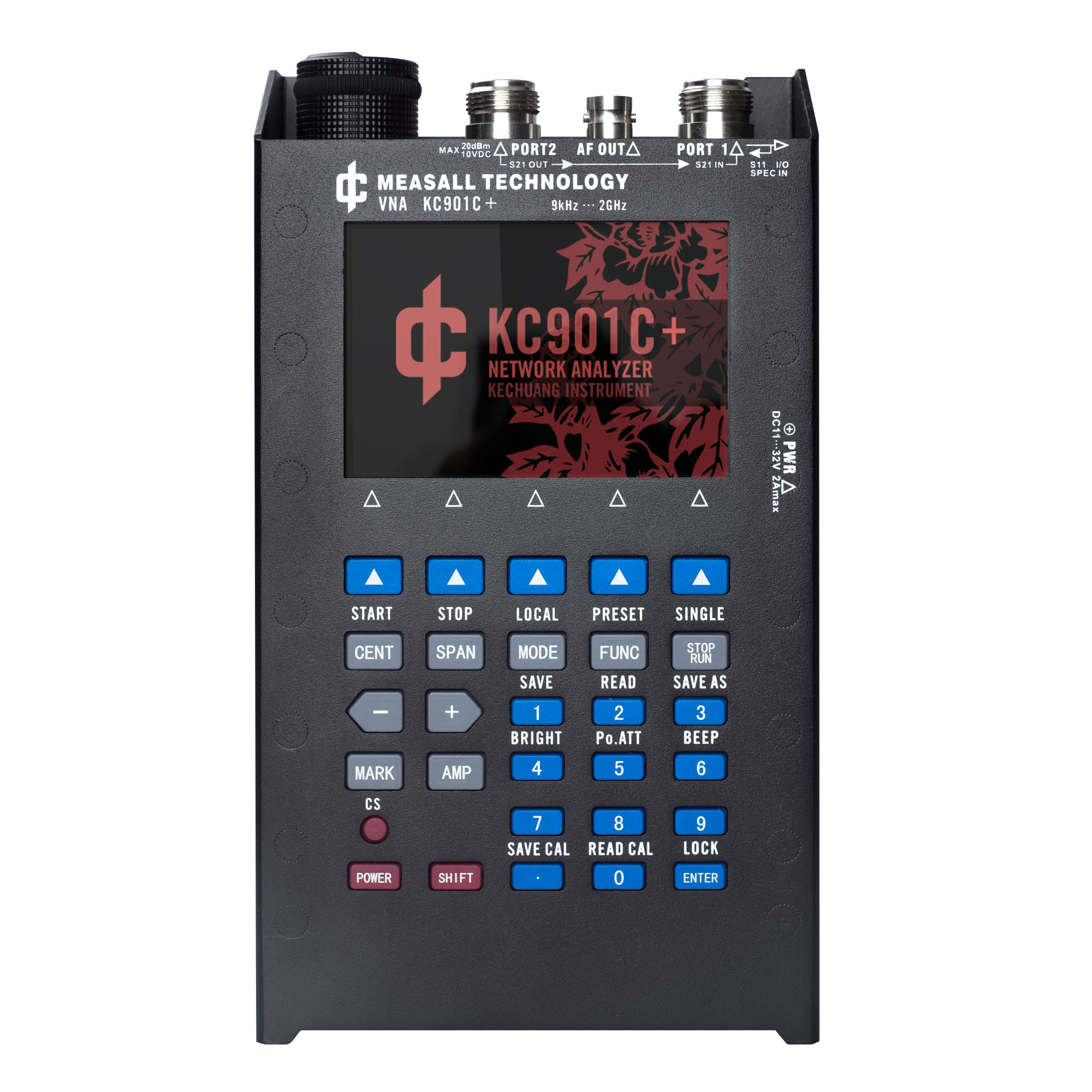
MEASALL Handheld Network Analyzer KC901C+ 2GHz VNA
$769.00 -
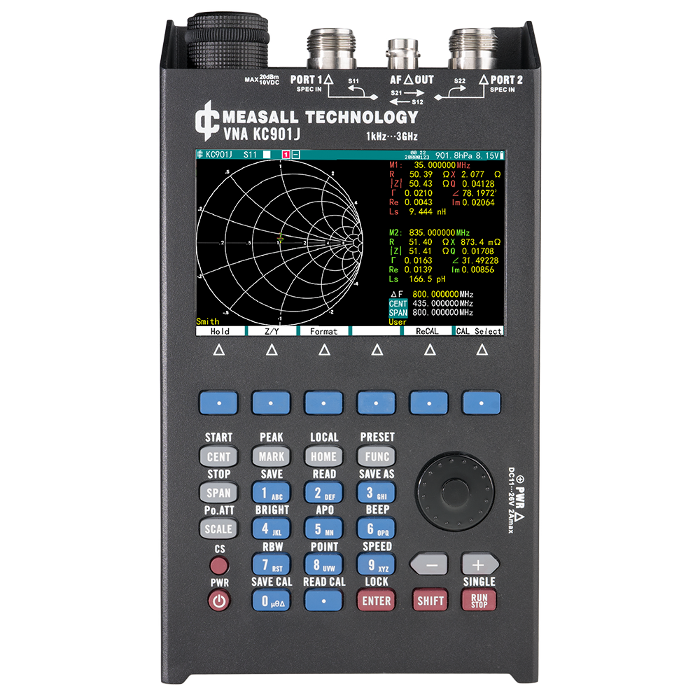
MEASALL Dual Ports Handheld Network Analyzer KC901J 1kHz-3GHz
$1,299.00 -
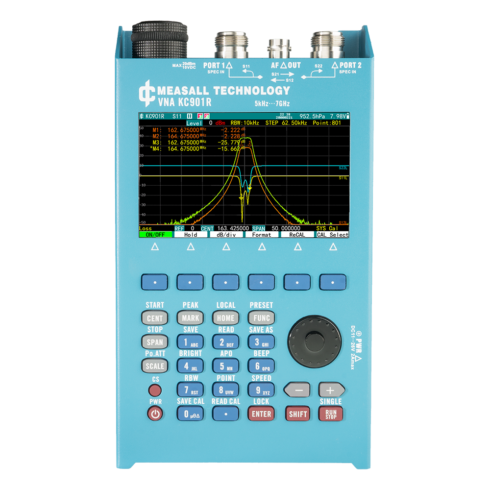
MEASALL Dual Ports Handheld Network Analyzer KC901R 5kHz-7GHz
$2,199.00 -
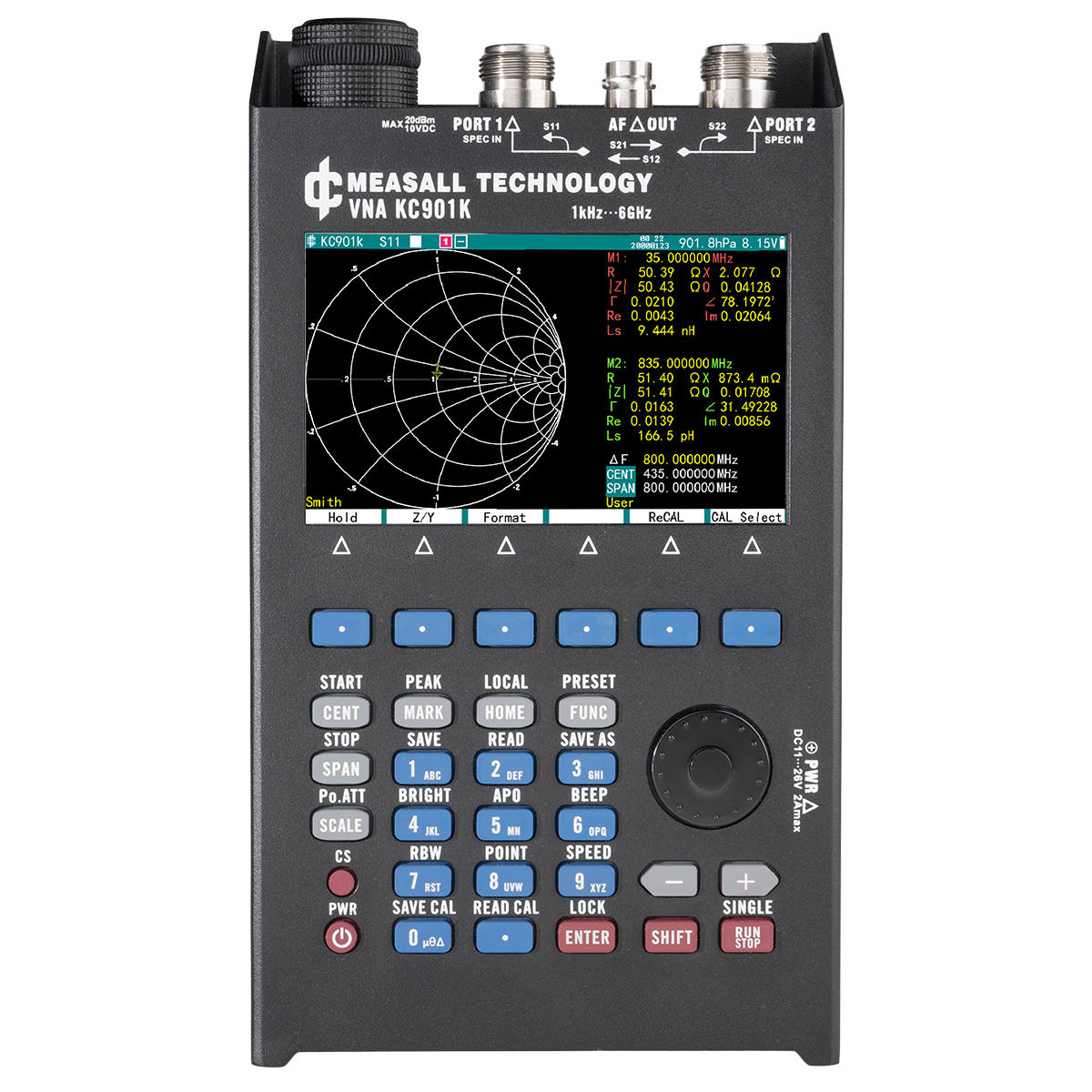
MEASALL Dual Ports Handheld Network Analyzer KC901K 1kHz-6GHz
$1,789.00 -

MEASALL Handheld Network Analyzer KC901Q 20GHz VNA
$3,999.00 -
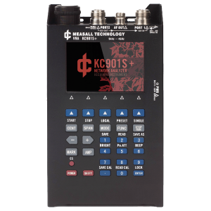
MEASALL Handheld Network Analyzer KC901S+ 9kHz-4GHz VNA
$1,299.00 -
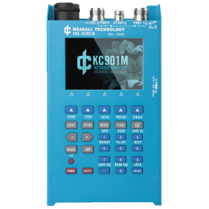
MEASALL Handheld Network Analyzer KC901M 9kHz-9.8GHz VNA
$2,199.00 -
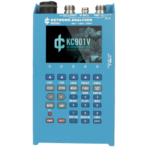
Handheld Network Analyzer KC901V 6.8GHz VNA
$1,899.00
