Description
KC980D and KCR100C refer to the same product. KC980D is the designation assigned under the updated model naming convention. The KC980 series also includes other variants—such as KC980A, KC980B, and KC980C—each covering different frequency ranges. KCR100C was designated under the previous naming system and is temporarily retained to assist customers with model selection.
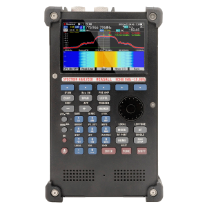
KC980X represents a series of directional antennas featuring a consistent handle design. They are primarily used as accessories for spectrum analyzers and reconnaissance receivers, supporting applications such as transmitter detection, radio direction finding, near-field electromagnetic interference (EMI) troubleshooting, and, for certain models, field strength measurement. This series is characterized by a wide frequency range, moderate size, ease of portability, and robust construction, making it well suited for handheld use in both indoor and outdoor environments.
As of now, the KC980X series includes the following models:
Model |
Type |
Frequency Range |
KC980A |
Shielded Loop |
9kHz~100MHz |
KC980R |
Shielded Loop |
20kHz~400MHz |
KC980B |
Hybrid Loop |
20~200MHz |
KC980S |
Hybrid Loop |
30~350MHz |
KC980C |
Hybrid Loop |
50~500MHz |
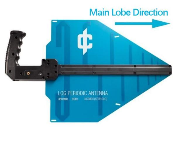
KC980D |
Log-Periodic |
350MHz~9GHz |
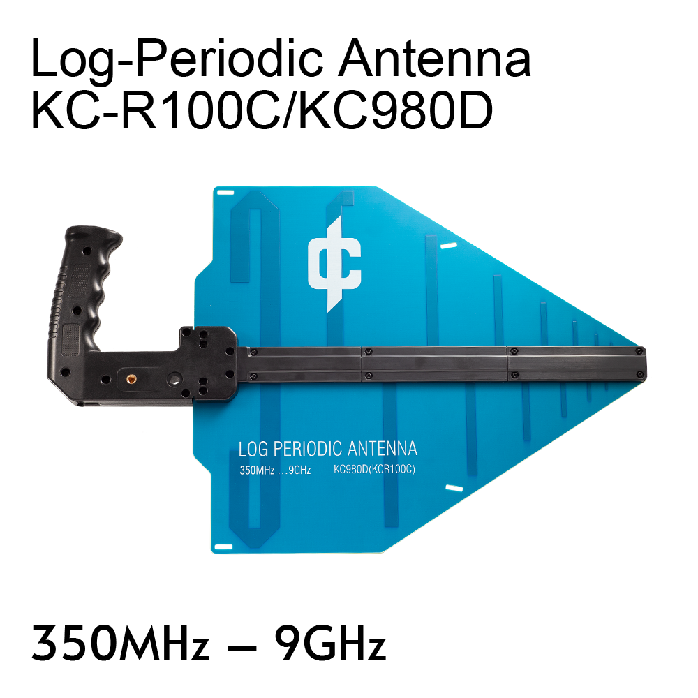
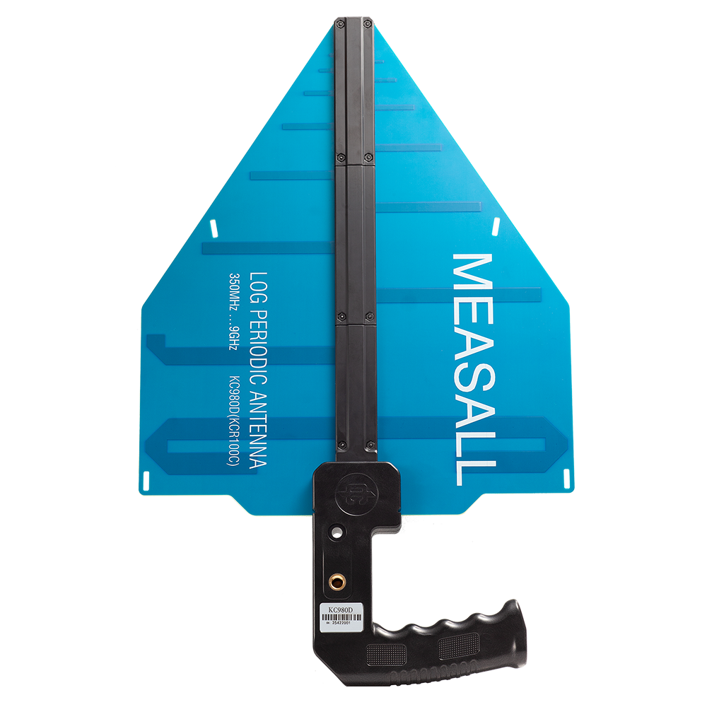
KC980D is a printed log-periodic antenna primarily designed as a supporting antenna for field strength meters, spectrum analyzers, and reconnaissance receivers. It is used for field strength evaluation, emission source detection, and radio direction finding. The antenna features a wide frequency range, moderate size, easy portability, and a robust construction, making it suitable for a variety of testing applications.
Frequency Range: 350 MHz … 9 GHz
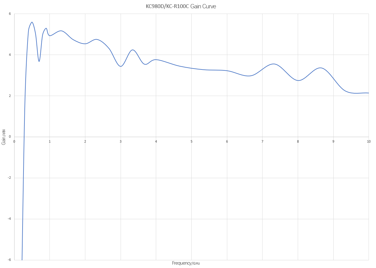
The KC980D performs reliably and effectively within the frequency range of 350 MHz to 9.0 GHz. Below 350 MHz, its gain drops rapidly, reaching approximately 0 dB at 300 MHz and about –8 dB at 200 MHz. Above 9.0 GHz, the return loss and gain decline more gradually. When performance requirements are less stringent, the antenna can be operated within a broader range of 330 MHz to 10 GHz.
Rated Gain: 3.5 dBi
Typical gain values of the KC980D start at 5.5 dB at low frequencies and gradually decrease as frequency increases, reaching approximately 2.5 dB at 9 GHz.
The gain exhibits rapid fluctuations across the frequency range, with an amplitude of about 2 dB. When using the antenna, its usability should be verified within a gain range of +3.5 dB to –0.5 dB as frequency rises.
The KC980D uses a coaxial cable for signal output; the gain values above are measured with the original cable. As a portable instrument, it is desirable for the cable to have low loss, high stability, and flexibility—though these three qualities often conflict. The KC980D employs a cable selected for balanced overall performance. If a different cable is used, please be aware that gain may vary accordingly.
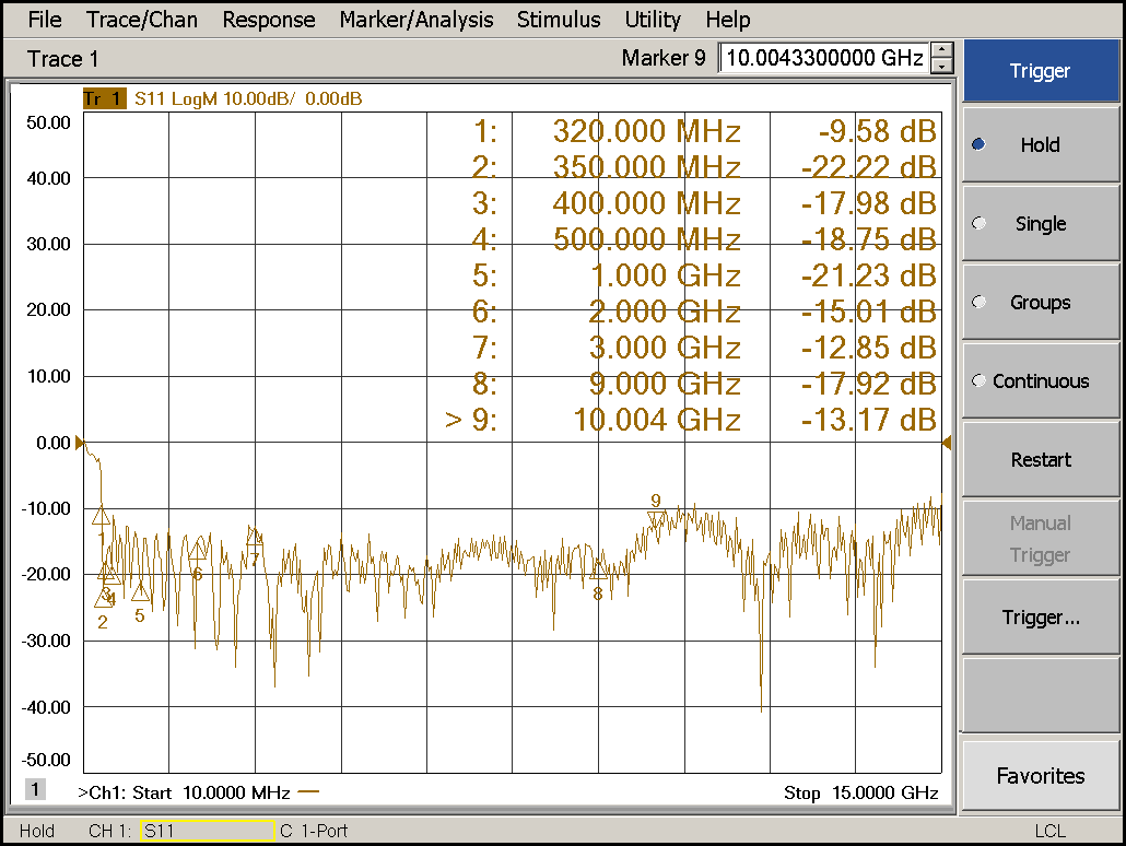
Return Loss: 13 dB
The antenna’s rated input impedance is 50 Ω. When matched to a 50 Ω source, the return loss varies but remains mostly around 13 dB or better, corresponding to a VSWR of approximately 1.6. Below 350 MHz, the VSWR increases rapidly.
Power Handling: 5 W
The KC980D can be used both as a receiving and transmitting antenna. When used for transmission, its power handling capacity depends on frequency: it is 25 W at lower frequencies (below 1 GHz) and 5 W above 1 GHz. We have performed stress tests at 50 W without damage; however, this is not guaranteed, especially at higher frequencies where power limits must be strictly observed.
As a receiving antenna, the maximum permissible power flux density in the antenna’s environment is 20 mW/cm² (continuous wave). Exposure to strong microwave radiation may cause the antenna to ignite.
Measured Sample Return Loss Plot
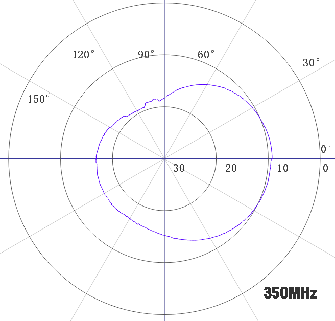
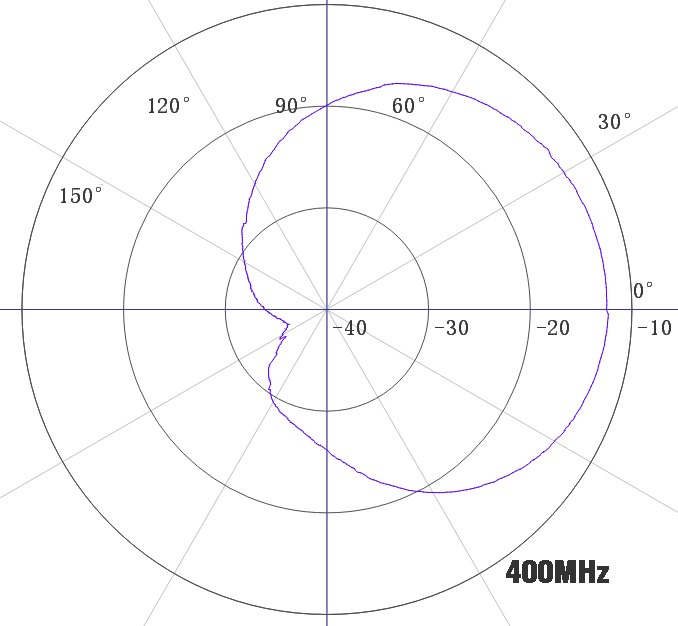
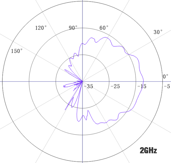
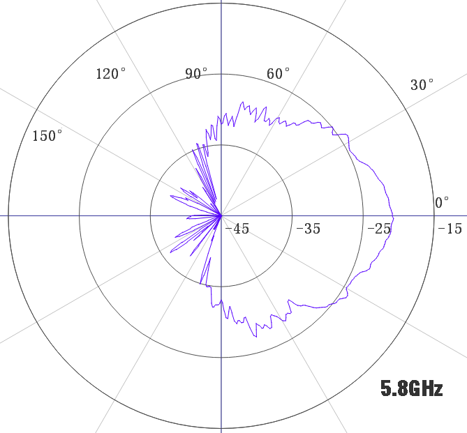
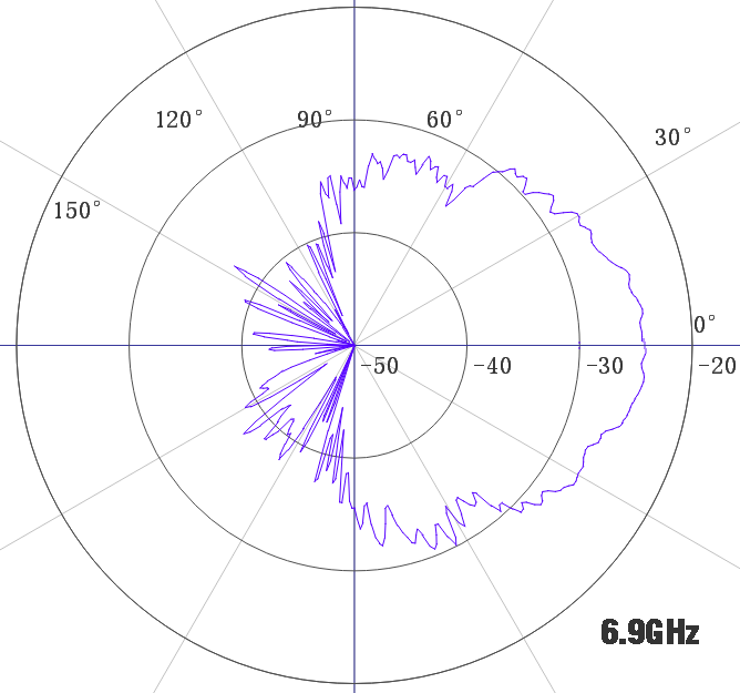
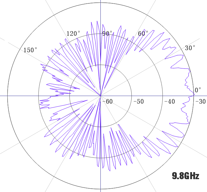
Directional Sensitivity
The KC980D can be used for direction finding across the frequency range of 350 MHz to 9 GHz. When held in one hand and rotated along with the user’s body, it exhibits high sensitivity to the direction of the transmitting source, making it suitable for progressive source localization. Within the 350 MHz to 7 GHz range, the antenna maintains good directionality regardless of human presence and is suitable for triangulation. Above 7 GHz, multiple narrow and strong sidelobes appear, and the main lobe may slightly split; therefore, practical experience and judgment are required during use.
*Test results are provided for reference only, as variations in mounting methods and the distance between the hand and body can affect the radiation pattern. Some curves display minor steps due to the testing system.
In all diagrams, 0 degrees corresponds to the geometric front; the coordinate radius (gain) is relative and carries no absolute value.
Mechanical Parameters
Name |
KC980D |
Remarks |
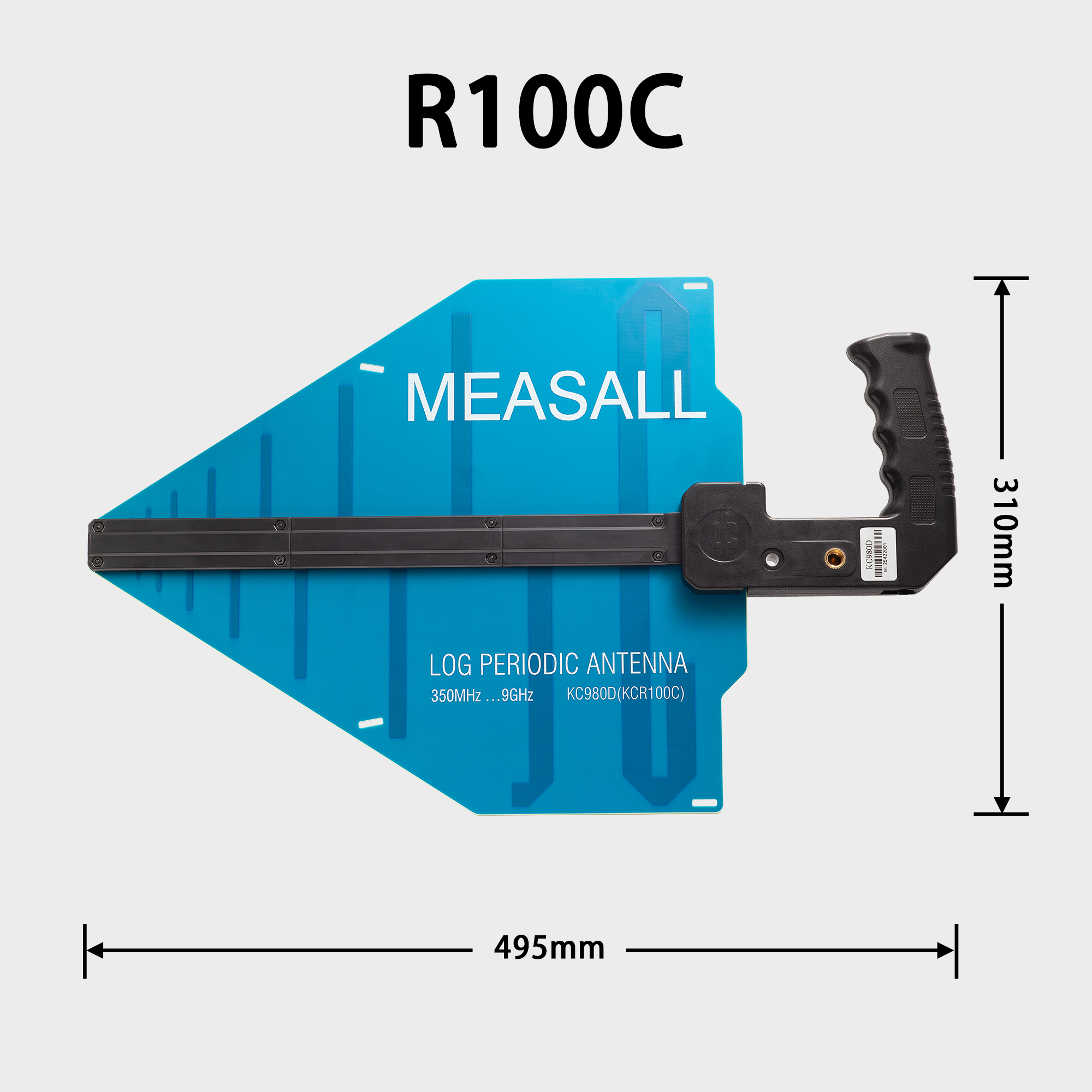
Dimensions/mm |
495×310×25 |
Excluding cable |
Cable Length/m |
Internal: approx. 0.45 m; external: approx. 1.35 m |
Measured from handle surface |
Net Weight/g |
660 |
Including cable |
Package Size/mm |
600×420×150mm |
Each box can hold 2 units |
Packaging Gross Weight/kg |
2.5kg |
When packing 1 unit |
Note: Parameters are subject to random variations and are for reference only.
4.Operating Conditions
Operating Temperature: -40 °C to +75 °C
Humidity Range: 0% to 95% (short-term exposure to 100% is acceptable, provided there is no direct water contact)
Water Resistance: After splashing, the antenna must be thoroughly cleaned and dried. Immersion may lead to water ingress into connectors and cables, compromising performance and lifespan; in principle, replacement is recommended.
Wind Resistance: For safety, use is prohibited when wind speed exceeds 20 m/s (equivalent to Beaufort scale 8).
5.Non-handheld Usage
The KC980X is designed primarily for handheld use and is generally not intended for fixed installation unless absolutely necessary. If installed in an outdoor environment that is sheltered from wind and rain, the usage duration should not exceed three days.
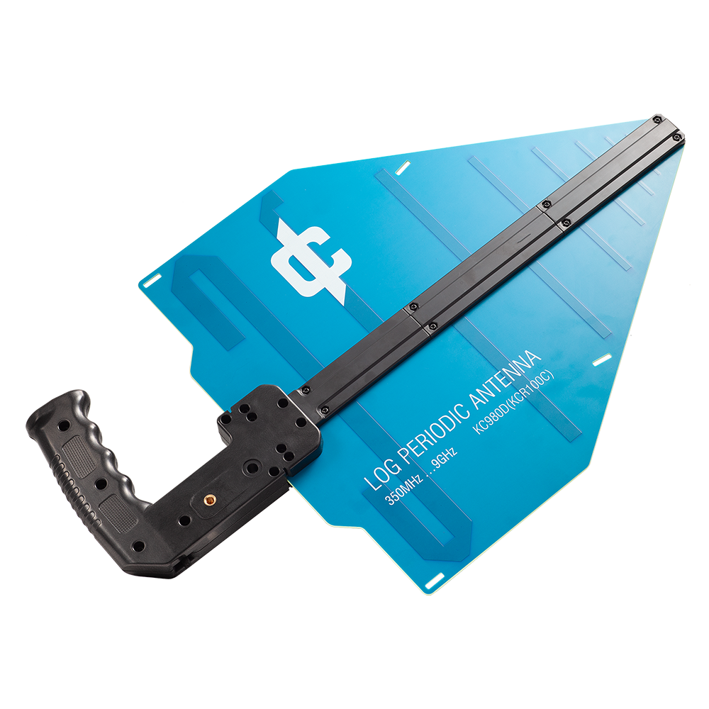
The antenna handle features two mounting screw holes. The 3/8-inch screw hole (on the left, the larger one) is used to secure the antenna and can be connected using appropriate photographic clamps. The 1/4-inch screw hole (on the right, the smaller one) is intended for attaching accessories (e.g., a smartphone holder) and is generally not suitable for mounting the antenna itself.
When using the mounting holes, ensure that the orientation of the antenna and handle allows the natural sagging tendency to align with the tightening direction of the bolt. The antenna must not be used in environments subject to vibration.
KC980D
Handheld Monitoring Antenna User Manual
https://deepace.net/wp-content/uploads/2025/06/KC980X-User-manual-6.24.pdf