Description
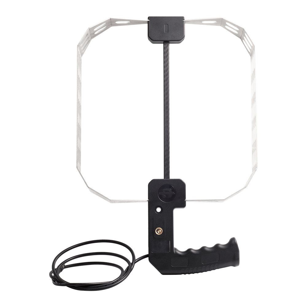
KC980X represents a series of directional antennas featuring a consistent handle design. They are primarily used as accessories for spectrum analyzers and reconnaissance receivers, supporting applications such as transmitter detection, radio direction finding, near-field electromagnetic interference (EMI) troubleshooting, and, for certain models, field strength measurement. This series is characterized by a wide frequency range, moderate size, ease of portability, and robust construction, making it well suited for handheld use in both indoor and outdoor environments.
As of now, the KC980X series includes the following models:
| Model | Type | Frequency Range |
| KC980A | Shielded Loop | 9kHz~100MHz |
| KC980R | Shielded Loop | 20kHz~400MHz |
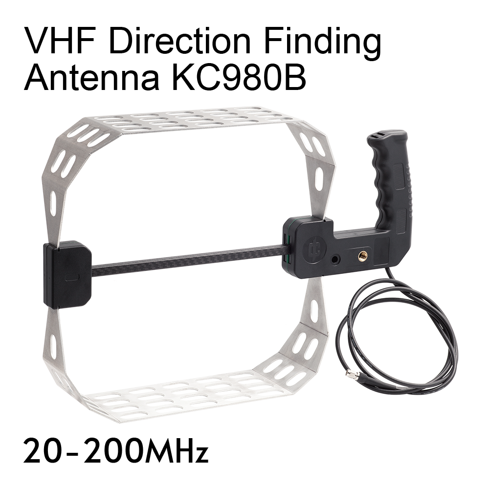
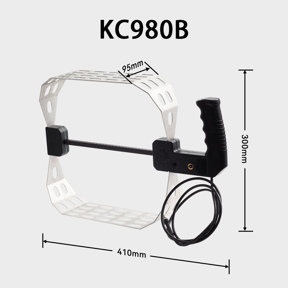
| KC980B | Hybrid Loop | 20~200MHz |
| KC980S | Hybrid Loop | 30~350MHz |
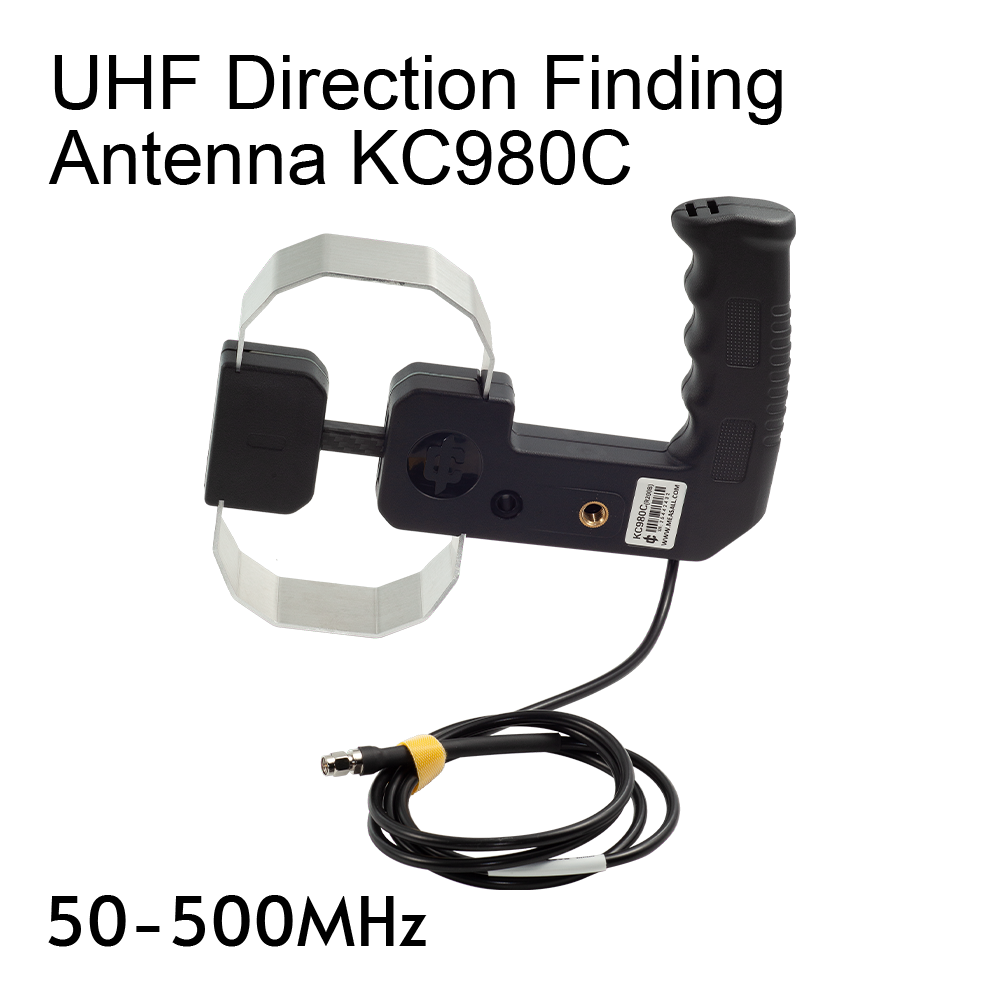
| KC980C | Hybrid Loop | 50~500MHz |
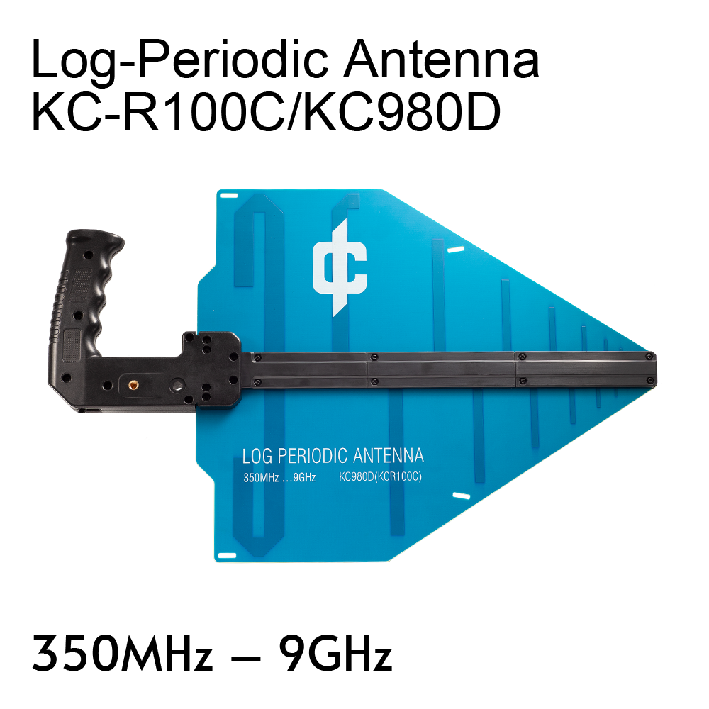
| KC980D | Log-Periodic | 350MHz~9GHz |
KC980B, KC980C, and KC980S
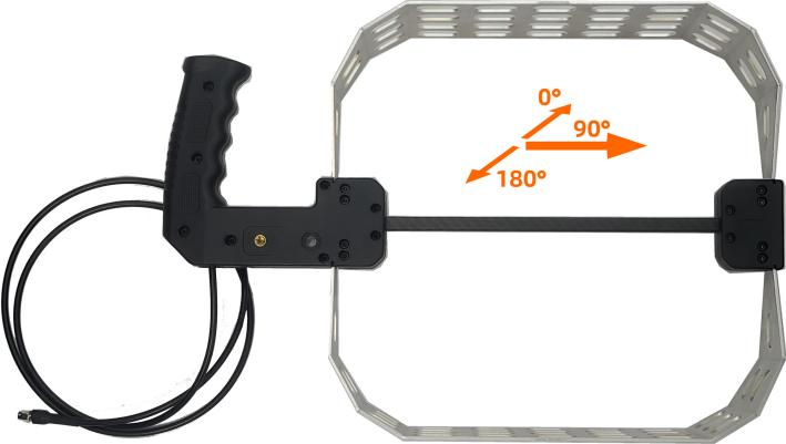
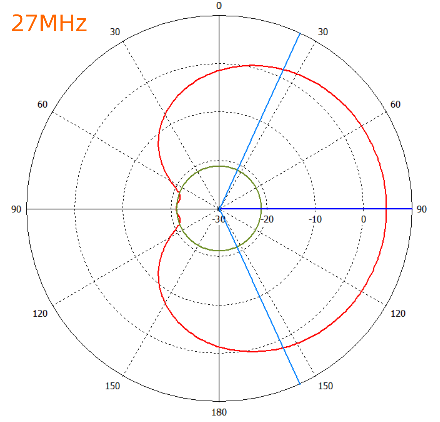
All are hybrid-field antennas. A loop with a circumference much smaller than the wavelength is typically a magnetic field antenna and should exhibit a figure-eight radiation pattern. However, if the loop is cut at the midpoint and a resistor is connected in series at the break, the dipoles formed on either side of the break respond to the electric field. Therefore, the response at the feed point is a combination of electric and magnetic field responses. Because these two responses have different phases, with an appropriately chosen resistor, the combined radiation pattern within the nominal frequency range changes from a figure-eight to a cardioid shape. This allows the antenna to be used for direction finding using the major lobe (strong signal peak) method, and at frequencies where nulls occur, the minor lobe (weak signal peak) method can also be applied. This type of antenna was invented around 1972 and is essentially the same as the historical shortwave direction-finding antenna composed of a loop antenna combined with a whip (rod) antenna.
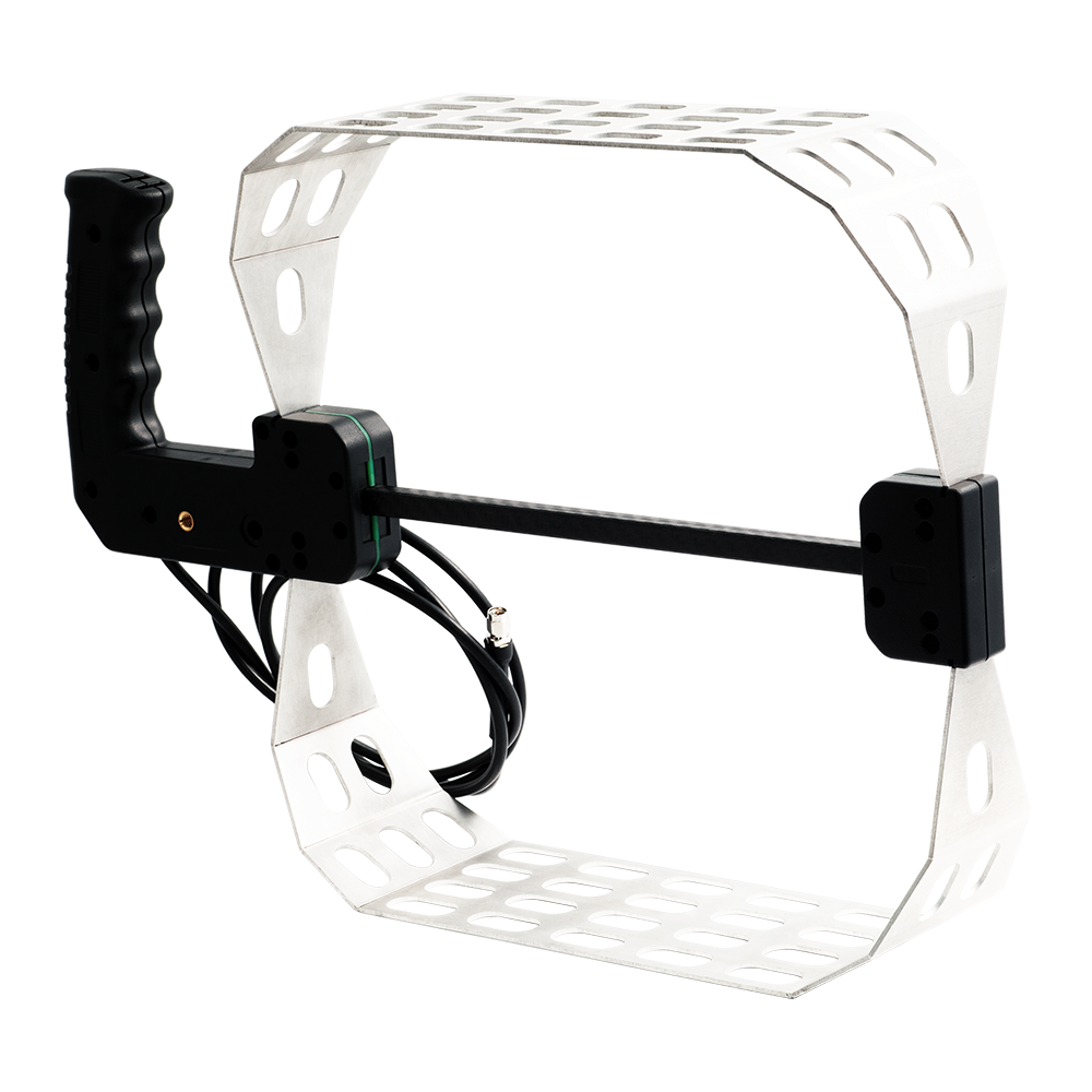
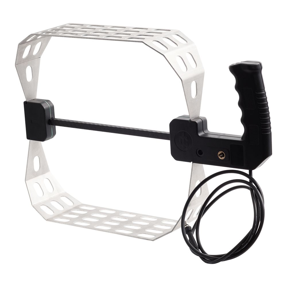
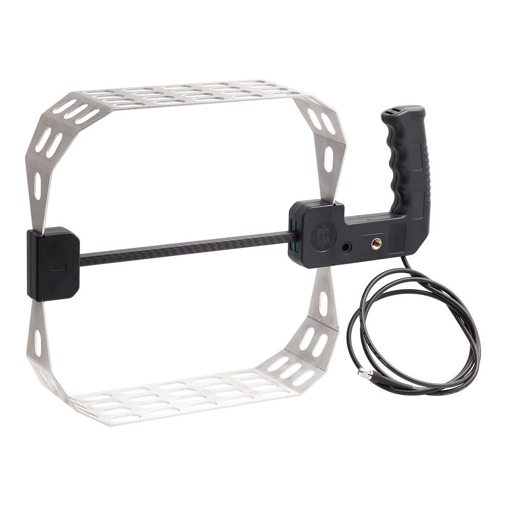
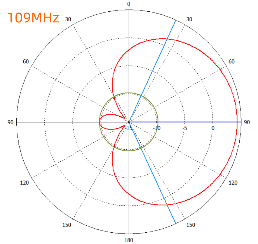
The circumferences of the KC980B, KC980C, and KC980S differ. The B model has the longest circumference, suitable for lower frequencies, exhibiting good directionality from 20 to 200 MHz. Above 250 MHz, the main lobe splits and gradually transitions to the radiation pattern of a dipole antenna. The C model has the shortest circumference, with acceptable directionality from 50 to 500 MHz; its main lobe splits at around 550 MHz, making it suitable for higher frequencies. The S model falls between B and C in circumference, and its gain is also intermediate. Below the lower frequency limit, the antenna behaves like a single-turn inductive coil, with the main lobe splitting and eventually forming a figure-eight pattern perpendicular to the antenna plane.
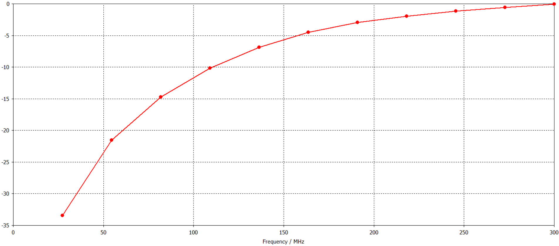
Gain
The antenna’s main lobe gain increases as frequency rises. The relative variation with frequency is illustrated in the figure below:
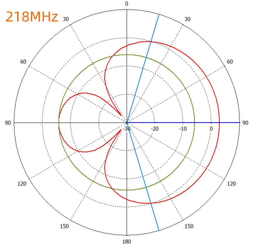
The theoretical directivity pattern of the KC980B is shown below; please note that the horizontal axis represents relative values only.
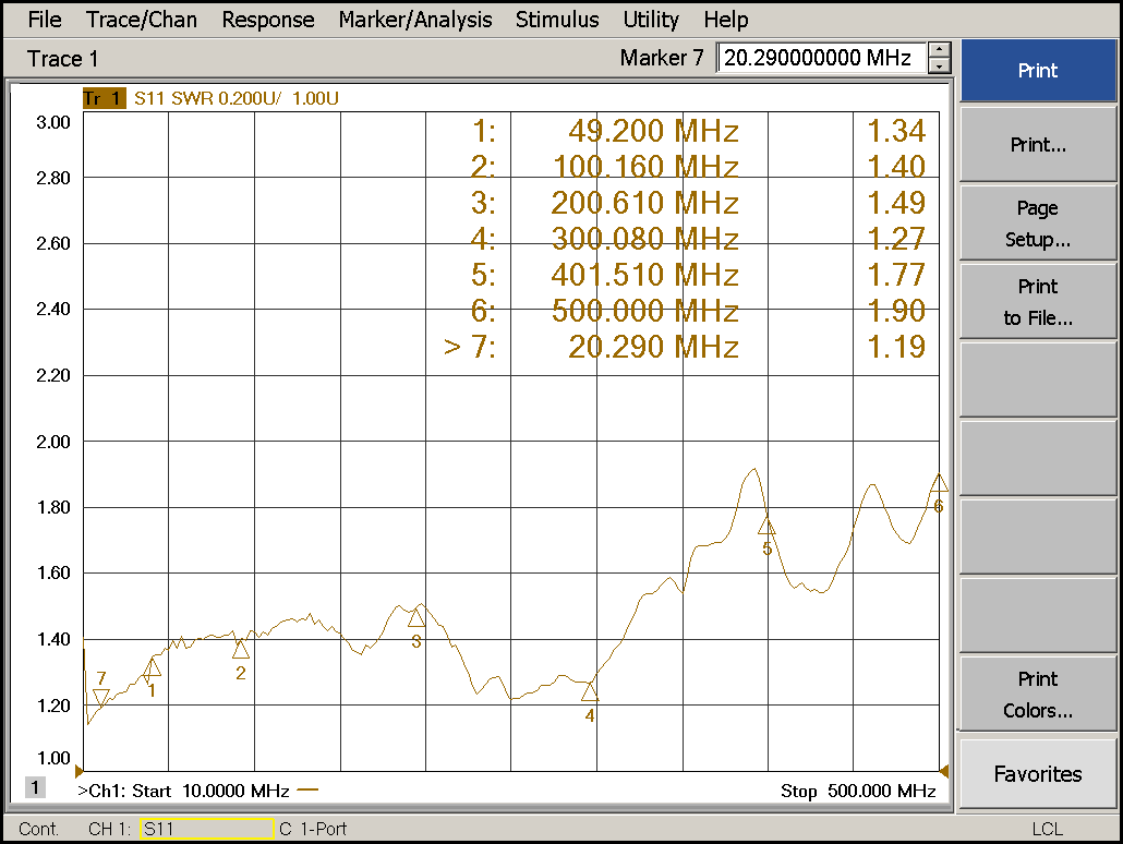
VSWR
Typical VSWR values are as follows:
Mechanical Parameters
| Name | KC980B | KC980C | KC980S | Remarks |
| Dimensions/mm | 430×295×90 | 220×210×40 | 305×210×40 | Excludes cable |
| Cable Length/m | 1.35 | 1.35 | 1.35 | Measured from handle |
| Net Weight/g | 800 | 350 | 405 | Includes cable |
| Packaging Size/mm | 520×360×130 | 365×265×85 | 365×265×85 | One piece per carton |
| Total Packaging Weight/kg | 1.5 | 0.8 | 0.9 |
Note: Parameters have some random fluctuations and are for reference only.