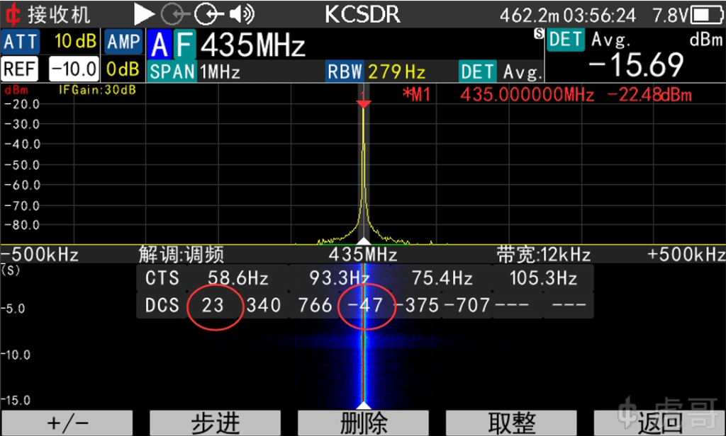
Continuous Digital Controlled Squelch System (CDCSS), also known as Digital Coded Squelch (DCS), is a commonly used squelch or call selection method in the analog communication era, and an early scheme was published in Mobile Radio Technology, 1990.
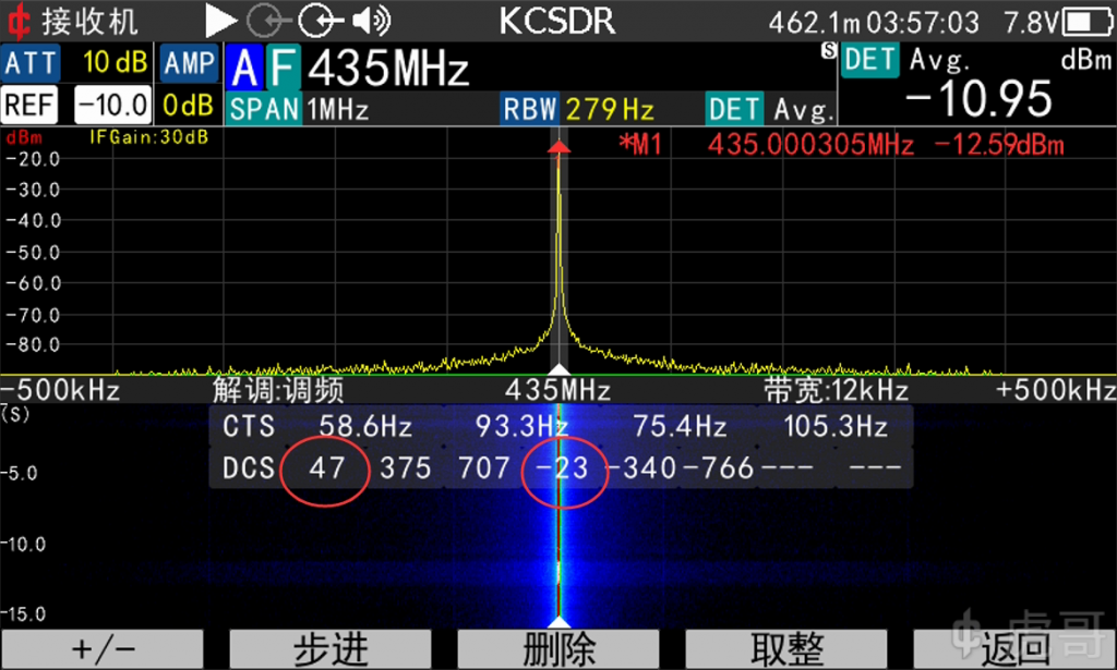
Since analog communication has nearly died out, this system is also considered to have completed its historical mission. However, the Tone Squelch analysis function of KC908 provides DCS decoding, and the decoding result is often different from the setting of the radio, so some people complain that the decoding of KC908 is wrong. So there is only one article to write, easy to take out at any time to explain to the user.
For the sake of common sense, the following description is not necessarily rigorous.
DCS sends a string of “digital signals”. Said “digital signal”, in fact, is in the analog radio transmission modulation of some high and low-level signals, modulation rate is 134.3bps. The use of such a low rate is to make the digital square wave by the low-pass, both to avoid crosstalk between the code, but also basically located in the frequency of 300Hz or less, so as not to interfere with each other with the voice. “Tone Squelch” means that the frequency is lower than the voice.
This string of “high and low levels” is the length of 23-bit Golay code. In the days of poor microcontroller performance, this approach favored the use of simple digital logic circuits for codecs and error correction.
However, when sending a DCS, there is no header and no tail, the radio will keep sending the 23-bit binary stream in a loop, and when receiving it, it does not know when the data starts. Then there are 23 possibilities for the start. To solve this problem to some extent, a flag bit “100” is set in the middle of the data. The 11 bits before the flag bit are check bits, and the 9 bits after the flag bit are data bits. This flag bit is always found by a constant cyclic shift during reception.
In this case, a total of 29 = 512 DCS codes are possible.
However, the “100” can occur in other places, for example in both data and check bits, and there are many cases where, assuming the flag is set incorrectly, the check and data still match perfectly. For example for DCS code 023:
11101100011-100-000-010-011 = 023
Shift 6 bits to the right and the “100” flag appears!
01001111101-100-011-100-000 = 340
Shift right another 10 bits and the “100” sign appears again
00111000000-100-111-110-110 = 766
And that’s not all. In the past, no one knew the polarity of the phase detector, and there was no standardization among manufacturers, so the polarity of the received code was not known. That is, a 0 could be a 1 and a page 1 could be a 0.
Continuing with the DCS code 023 example:
11101100011-100-000-010-011 = 023
If the polarity is reversed, it becomes:
00010011100-011-111-101-100
Note that the original 100 flag bit is corrupted and cannot be decoded. However, since it is not known when the data started, the receiver must keep shifting until the 100 flag bit appears.
After shifting, these results are obtained:
11101100000-100-111-000-111 = 707
10000010011-100-011-111-101 = 375
00011111101-100-000-100-111 = 047
When all these surprises are eliminated, there are about 200 DCS codes left.
However, there are still a lot of imperfections in the remaining codes, such as the possibility that it may have a harmonic component that can just reach the analog squelch level, or that too many 0s or 1s can cause severe distortion (which the modem’s scrambler is designed to solve), or that there is no 100 flag bit if the polarity is reversed (meaning that if it is reversed, there is no way to remedy the situation). When the results are eliminated, there are over a hundred usable DCS codes left, of which 83 groups are usually used.
However, as an instrument, all possible codes should be decoded and displayed, except for a few exceptions (e.g., all zeros or all ones). With artificial filtering, in case any system uses a code that is not commonly used, it will not be able to decode it!
Therefore, the KC908 will decode all possible codes in positive polarity, and then switch to negative polarity to decode the other half of the possible codes. And the code that is in the middle of the 83 groups in the result of positive polarity decoding will be in the top of the list.
Many radios nowadays can be set for DCS transmit polarity. But this polarity on a radio is defined by the manufacturer and is not an absolute concept. This vendor’s positive polarity may well be that vendor’s negative polarity. For example, two household name equipment vendors in Japan (Y & I) have opposite polarities.
For greater versatility, a radio’s setup program usually also has a receive polarity setting. Amateur radio stations usually have a “both” option in the receive polarity setting, which means that the squelch is released if one of the polarities is correct, regardless of the polarity, e.g., both 023 and 047 can be turned on in the both state.
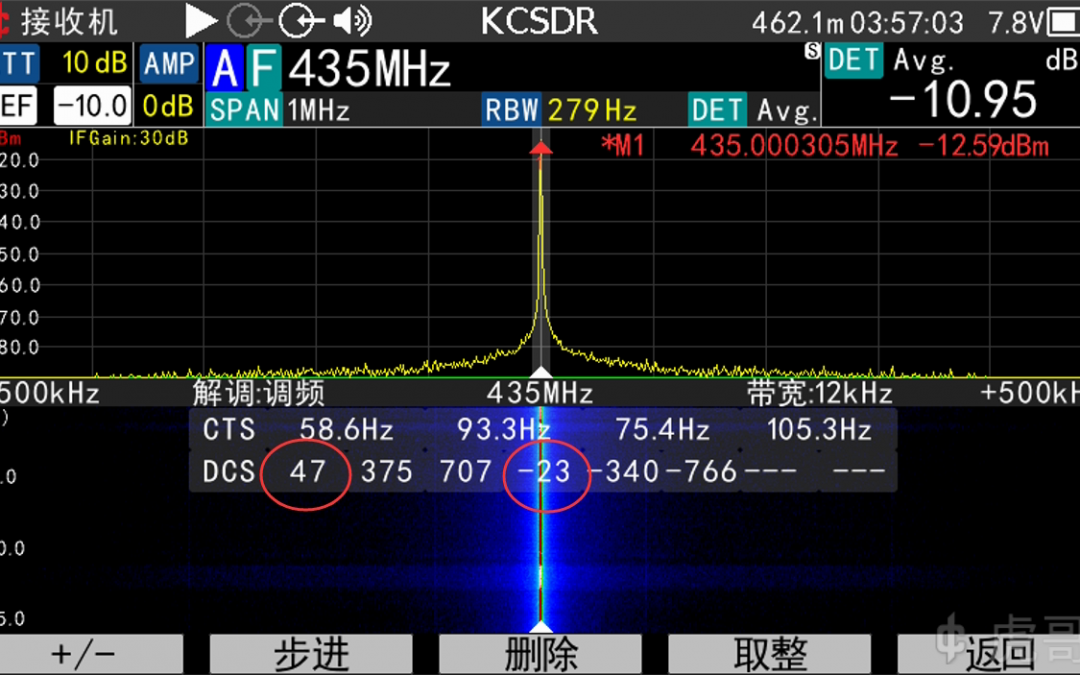
Therefore, if a radio set to DCS023 transmits, KC908 may first display 023 or 047, don’t think 047 is wrong, he is the correct result. And in the decoding list, it will definitely give the reverse polarity result like -047 or -023. The user just decides which one to believe.


