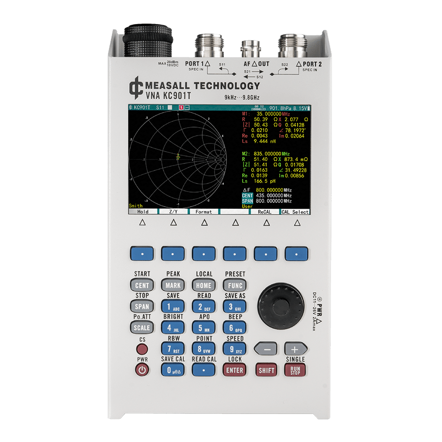
2 Ports Handheld Vector Network Analyzer
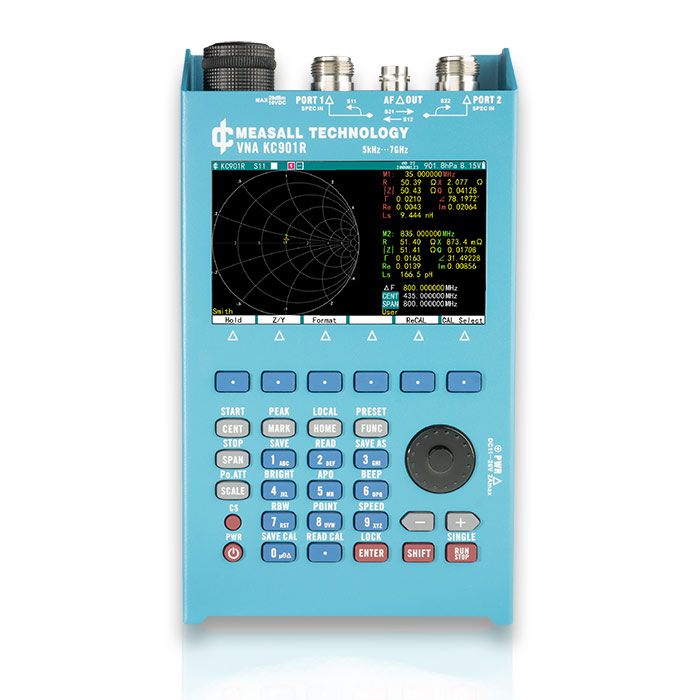
KC901 J/K/R/T/B

Product Highlight
- 5 kHz to 2/4/7/10/22 GHz
- S-parameter (S11, S12, S21, S22) and time domain measurement
- RF/AF generator, dual-port comparator, field meter, spectrum function
- 100 dB(typ.) transmission dynamic range and 42dB directionality
- Temperature-compensated high-precision measurement
- Ethernet and USB data connection
All-in-one RF measurement instrument
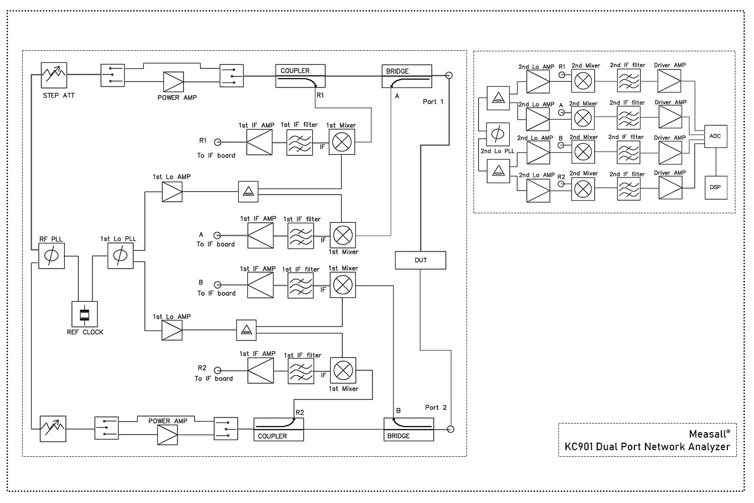
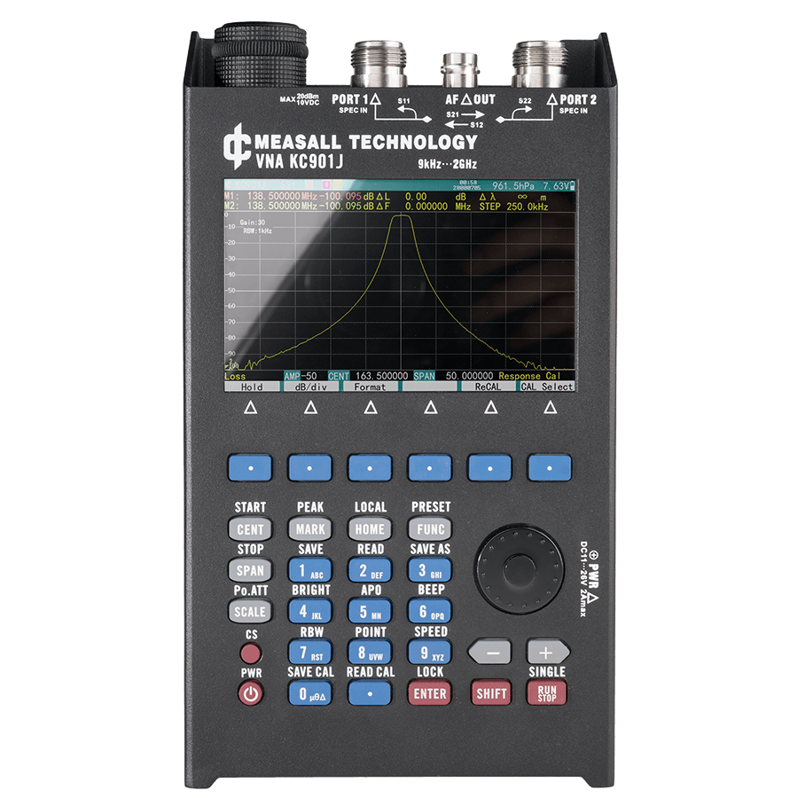
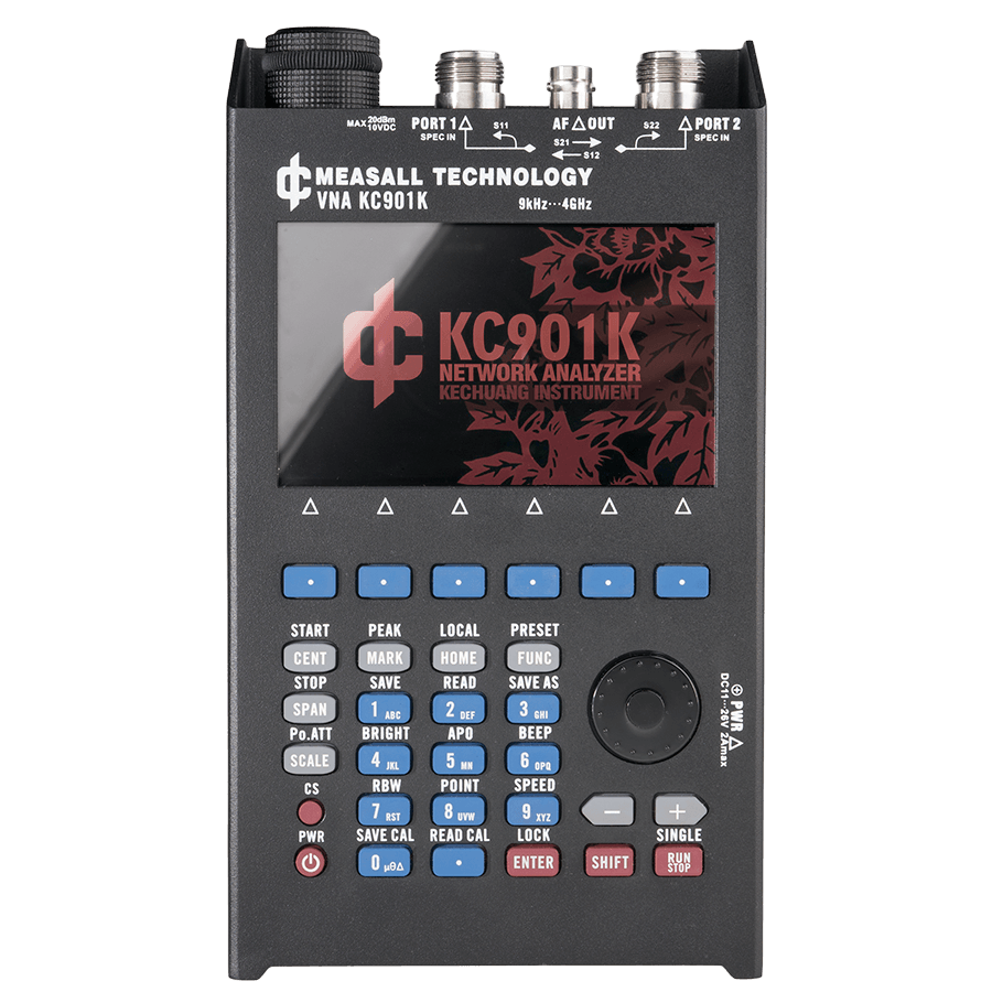
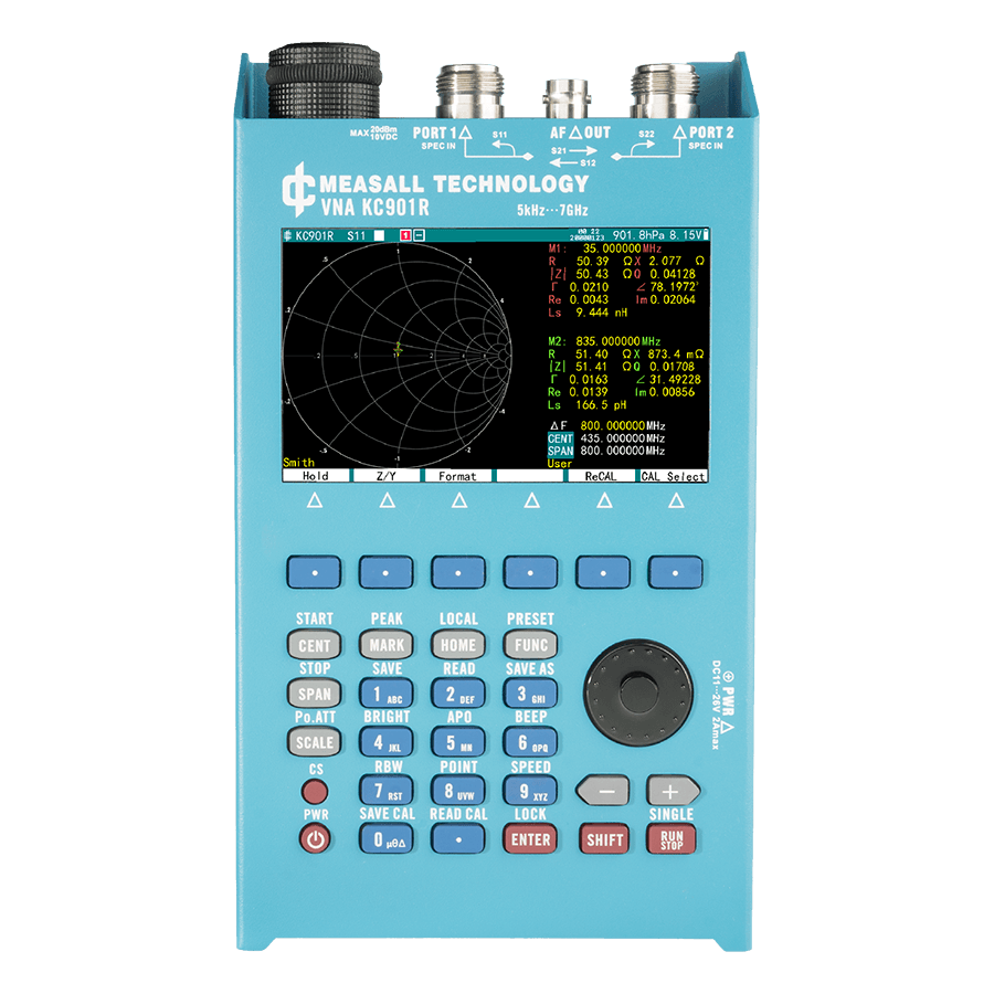
4th KC901x is a RF multi-meter based on the network analyzer architecture. Five models covering the frequency 5kHz to 22 GHz. The main feature of the KC901x is a full dual-port VNA, extend time domain(distance to fault point), simple spectrum display, field strength meter, RF source, AF source, and dual-port comparator utility functions based on the network analyzer architecture.
Document and files
4th KC901 Overview
4th KC901 Manual
KC901x Program manual
Firmware update
Portable and User-Friendly
KC901 is made for portability, with minimal volume and weight advantages in the same class of instruments, very suitable for field experiments, on-site construction and other uses. With the built-in lithium battery and easy operating design, It can support a full day of intense measurements. With USB Type-C charge ability makes engineer do not need to carry a DC adapter.
No-compromise RF performance
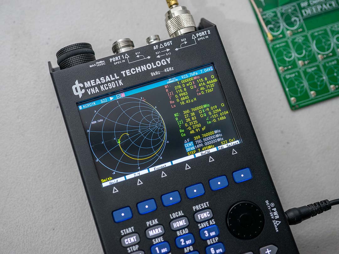
Precision RF front-end circuitry coupled with a high-performance ADC, enabling it to achieve trace noise levels <0.005dB . Anti-crosstalk circuit design and strict shielding allows the KC901 to obtain a better dynamic range of transmission measurements.

Expand Instruments with Free Software
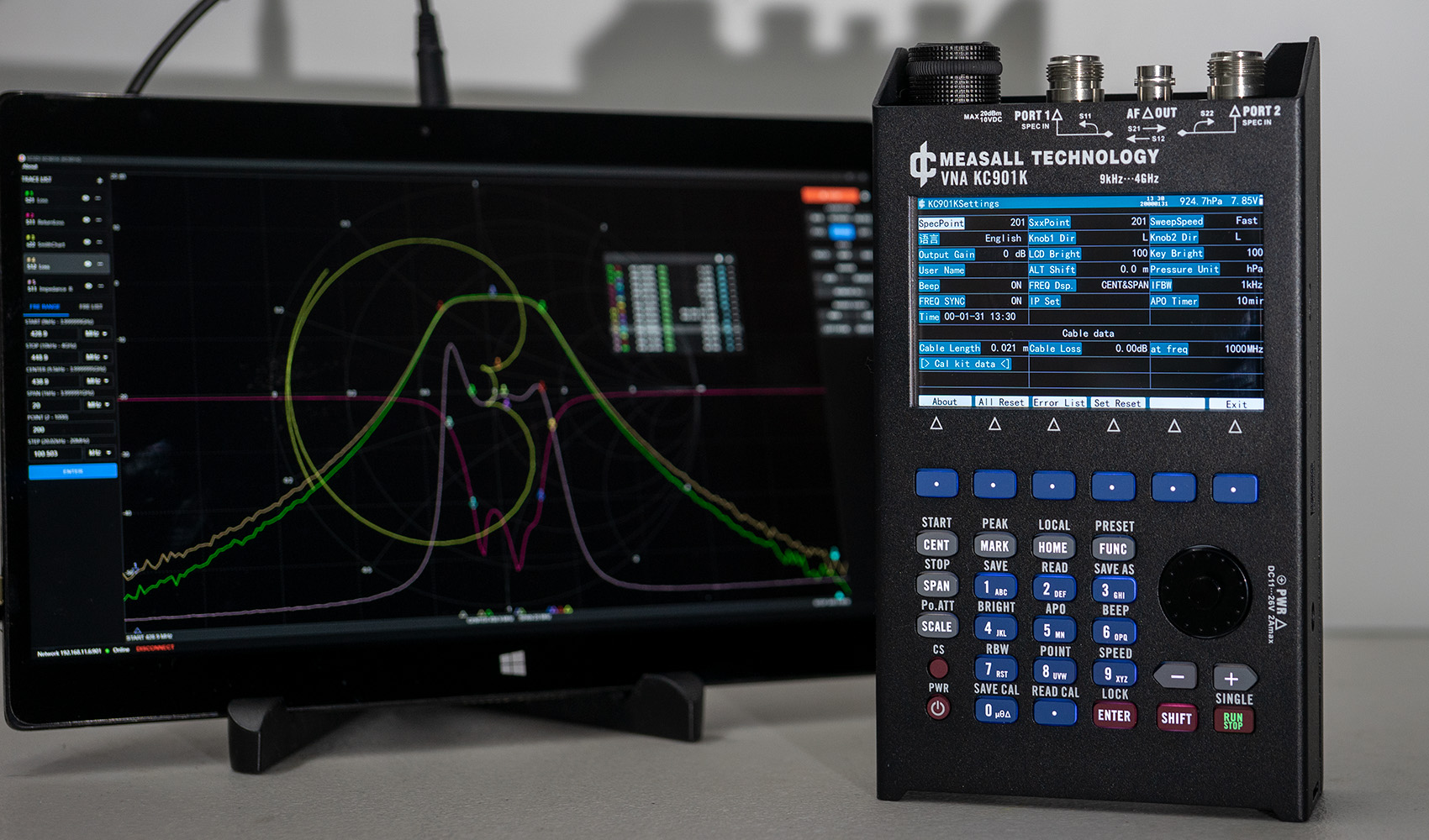
Free KCSDI software makes it easy to expand the measurement capabilities in the lab and measure remotely via an Ethernet connection.
We also provide the programming manual, you can connect the KC901 via RJ45 or usb and integrate it into your test solution.
Distance-to-Fault (DTF) Function
The DTF function is a powerful tool for detecting and pinpointing faults, breaks, or impedance mismatches along RF transmission lines. Perfect for installation, maintenance, and troubleshooting, it allows users to quickly locate cable issues, reducing downtime and ensuring signal quality. This feature is ideal for telecom technicians, broadcast engineers, and RF field engineers who need precise, reliable fault detection in coaxial and other transmission cables.

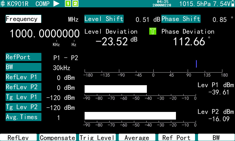
Comparator Function
The Comparator function allows for accurate phase and level comparisons between two ports, making it ideal for tuning phased arrays and other phase-sensitive RF systems. When used with a directional coupler, it can monitor forward and reflected signal power, providing critical insights into system performance and ensuring optimal alignment and signal integrity.
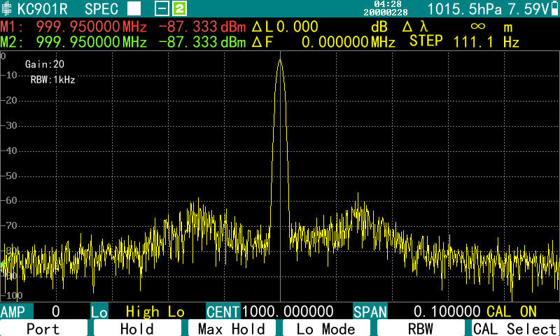
Spectrum Function
The Spectrum function leverages the VNA’s architecture to provide basic spectrum analysis capabilities, suitable for stable signal measurements. While not as advanced as a dedicated spectrum analyzer, it effectively handles many standard spectrum measurements, making it a practical tool for identifying and assessing steady RF signals in various applications.
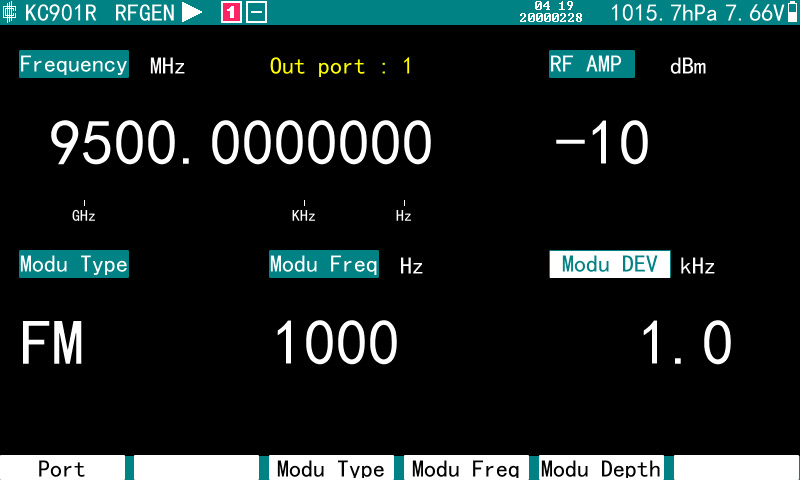
RF Source Function
The RF Source function generates reliable RF signals with support for continuous wave (CW) output and FM/ASK modulation, providing flexibility for various testing scenarios. It includes a 60 dB attenuation range, allowing precise control over signal strength, making it ideal for calibration, component testing, and system integration in RF applications.
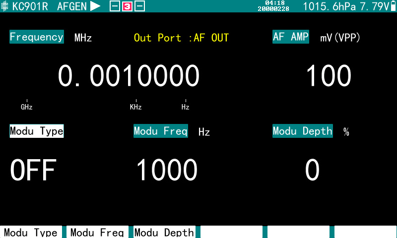
AF Source Function
The AF Source function generates audio frequency signals with support for continuous wave (CW) and FM/ASK modulation. It provides flexible routing options through either the BNC or RF port, making it versatile for audio signal testing, modulation experiments, and other applications that require low-frequency signal generation.
Order link
4 models cover different frequency ranges. Aside from the differences mentioned above, all the released models of the KC901x have the same basic functionality.
Technical Parameters
The technical specifications of KC901x are basically the same, with slightly different output levels for different models. This table is for selection reference only, subject to the parameters contained in the datasheet.
| KC901J | KC901K | KC901R | KC901T | KC901B | ||||
| Sweep speed | RBW=30kHz, per point | 0.5ms | When dual ports calibration is turned on, speed reduced to ½. | |||||
| RBW=3kHz, per point | 1ms | |||||||
| RBW=1kHz, per point | 2.6ms | |||||||
| RBW=300Hz, per point | 7.3ms | |||||||
| 10kHz,201pt per screen | 0.12s | |||||||
| Output level for all modes (set to maximum gain) | 1MHz-4GHz | 3dBm | 13dBm | |||||
| 4GHz-6GHz | 0dBm | 0dBm | 10dBm | |||||
| 6GHz-10GHz | -3dBm | 10dBm | ||||||
| 10GHz-22GHz | 6dBm | |||||||
| Output adj. range | 60dB | 45dB | ||||||
| Noise floor | 1MHz-4GHz | -107dBm | -113 dBm | RBW=1kHz | ||||
| 4GHz-6GHz | -100dBm | -100dBm | -110 dBm | |||||
| 6GHz-22GHz | -90dBm | -100 dBm | ||||||
| Dynamic range for transmission measurements | 1MHz-1GHz | 100dB | — | |||||
| 1GHz-4GHz | 93dB | 110dB | ||||||
| 4GHz-10GHz | 90dB | 80dB | 100dB | |||||
| 10GHz-22GHz | 80dB | |||||||
| Transmission uncertainty | 1MHz-10GHz | ± (0.2+0.02L) | >Dynamic range+20dB | |||||
| 10GHz-22GHz | ± (0.3 + 0.02 L) | |||||||
| S11 uncertainty | 3dB<RL<25dB | ± (0.5 + 0.1 RL) | <20dB | |||||
| S11 directionality | After calibration | 42dB | NA | |||||
| Phase Uncertainty | 100kHz-1GHz | 2° | Return loss <20dB | |||||
| 1GHz-10GHz | 5° | 7° | 5° | |||||
| 10GHz-22GHz | 15° | |||||||
| VSWR of the port | 1MHz-10GHz | 1.5 | static | |||||
| Tracer noise | RMS value | 0.005dB | 0.01dB | Loss <10dB | ||||
| IF Feedthrough Suppression | 30dB | |||||||
| Frequency stability, per year | 1ppm | |||||||
| Supply voltage | DC | 11V-32V (charger socket), 5V (Type-C port) | ||||||
| AC Power Adapter | 105V-230V | |||||||
| Battery | 6.5V-8.4V | |||||||
| Damage level | All Ports | DC15V, +20dBm | ||||||
| LCD resolution | 800×480px | |||||||
| Dimensions | 200×114×46mm (L×W×T) | |||||||
| Weight | Include battery | 1.3kg | ||||||
| Package standard | 2.5kg | |||||||
NOTE: Unless otherwise noted, metrics are measured in medium speed mode, with an analytical bandwidth (RBW) of 10 kHz, output attenuation of 0, temperature of 25°C, and calibrated by the user. A few occasional or permanent anomalous data segments may be outside the range of the parameter.
Connect with us
Get in touch with our engineers anytime, by email, live chat or phone. Our engineer team is always available to answer your questions.


