Portable antenna analyzer has been rapidly popularized in recent years, which brings great convenience for testing. However, people pay little attention to the testing method, and when judging the “superiority” of an antenna, they often twist the antenna to the antenna analyzer, and then draw the conclusion hastily. Some careful testers may use different instruments to compare with each other, they are often surprised to find that the test results are very different, and then to the larger, more expensive prevail. This article explores these topics.
1, the vast majority of whip antenna is unbalanced antenna, antenna analyzer shell will become part of the antenna.
Common handheld radio antennas and car suction cup antennas are only “antenna”, but no ground. Dismantling one of these antennas reveals that the connector’s core pin is connected to the antenna’s oscillator, while the shell is not connected to anything. This is like a light bulb, only the positive terminal and not the negative terminal, will not work. Then it is what for “ground”?
For the radio antenna, the shell of the radio is equivalent to the ground of the antenna. A more accurate statement is that when a person holds the radio and the shell of the radio to form a whole, the antenna is in the system formed by the radio and people work. For a vehicle-mounted suction cup antenna, the base of the suction cup and the roof of the vehicle form a whole, and the suction cup antenna must work properly in such a whole environment. When designing the antenna, it should be optimized under the rated operating conditions, and the design conditions should be observed when in use; if it deviates from these operating conditions, the performance of the antenna will be deviated.
On the other hand, a good antenna should be designed according to the common environmental conditions under which it operates, not according to some ideal conditions. On the one hand the antenna should radiate as well as possible, on the other hand it should be less sensitive to its surroundings – but the two are often in conflict. Good antenna design must find the optimal balance between many mutually constraining factors, rather than being accomplished with an ideal simulation in simulation software.
Understanding the above, it is clear why different antenna analyzers can measure the same antenna with wildly different results. Various antenna analyzer shell size and shape is different, of course, the “ground” is different, obviously difficult to get the same results. Larger instruments, such as tabletop VNAs, have a more “ideal” “ground” and therefore often appear to be more reliable.
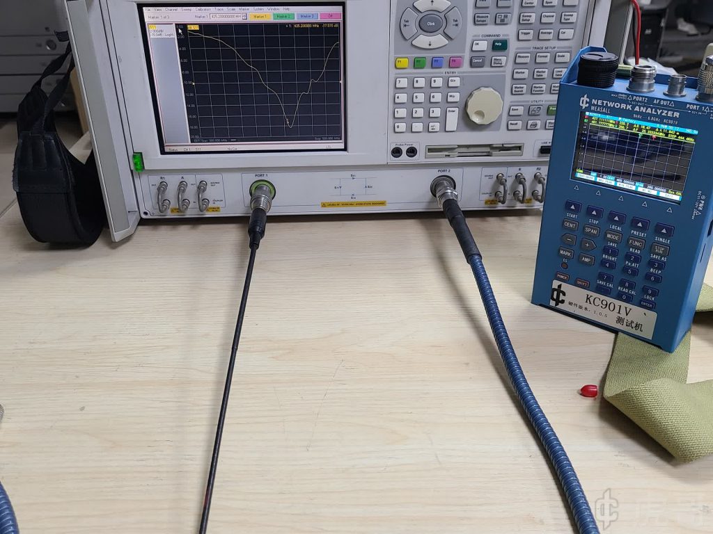
To illustrate this visually, we compare a hand-held VNA with a benchtop VNA, measuring a whip antenna and testing the return loss (or VSWR) parameter.
(pic1)
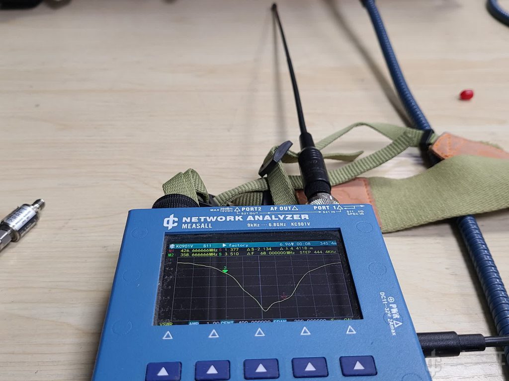
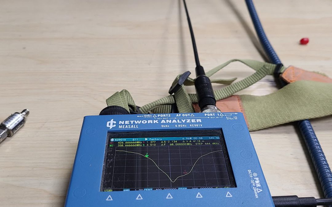
Laying the antenna flat on a table, you can see that its “resonance” point is at 401 MHz.
(pic2)
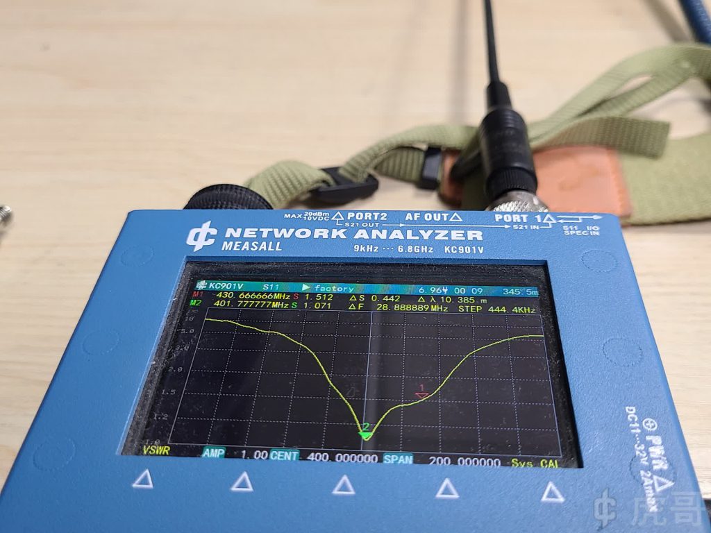
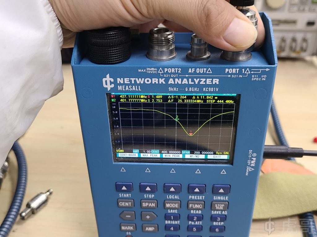
Placing the antenna and the instrument vertically on the table, the “resonance” point runs to 430.6MHz.
(pic3)
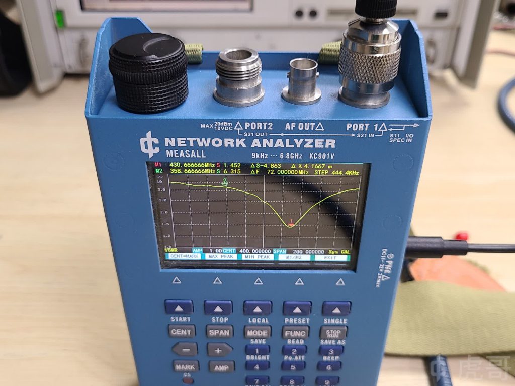
Squeezing the shell of the antenna by hand and forming a “whole” with the antenna analyzer, the “resonance” point runs to 427 MHz.
(pic4)
The same position gives different results on a desktop VNA.
(pic5)
The “resonance” point becomes 425 MHz (cursor 1).
(pic6)
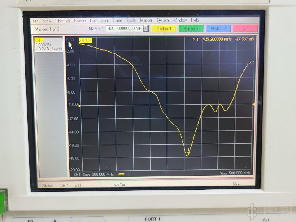
These tests show that measuring the same antenna with different instruments does give completely different results.
One might point out that none of the instruments were calibrated. In fact, calibration or not, will not affect the measurement of the VSWR minimum frequency, if only look at the frequency then calibration is irrelevant.
2, VSWR minimum point is not necessarily resonance point
Above, but any mention of resonance, are added in quotes, because those VSWR minimum frequency, not necessarily the resonance frequency of the antenna, said it “resonance” just to mock this common error. For an antenna, resonance is defined as the offsetting of the capacitive and inductive reactances at the feed point, manifesting itself as pure resistance. How many ohms this “resistance” is depends on the form of the antenna and the operating environment. For example, the resonance resistance of a half-wave dipole is about 70Ω, which is not equal to 50 ohms. When connected to a 50 ohm radio or analyzer, its VSWR is very large and not equal to 1. Of course, it is often desirable to design an antenna to resonate at a commonly used frequency and keep the resonance impedance close to 50 Ω, and then, if that is not possible, to convert it to 50 ohms by means of impedance matching to improve performance. But this is usually difficult, especially with small whip antennas.
In other words, the point of minimum VSWR is simply the point at which the antenna is best matched, and should be called the matching point, not necessarily the resonance point. To know the resonance point, you need to calibrate the instrument to the feed point, and then find the frequency where the reactance is zero.
3, VSWR minimum point is not necessarily the “effect” of the best points
Antenna “effect” by many factors, in addition to the size of the above mentioned VSWR, more important is the antenna’s directionality, VSWR is not necessarily the smallest point of the best directional point. Directionality originally includes two layers of meaning, the first is the size of the radiation (gain), the second is the direction of radiation, or the main beam direction. The frequency with the smallest VSWR does not necessarily have the highest gain. At the frequencies with the highest gain, the antenna’s main beam direction may not be aligned with the object of communication.
Whip antenna is usually used for mobile devices, his use is characterized by the communication object is not fixed, the placement of the position may change at any time. Under these conditions, the antenna gain if too large, a little “hand shake”, the signal strength will fluctuate greatly, and not much practical significance. Therefore, the antenna of a handheld device often only needs a low gain, and it is expected that it is in the VSWR minimum, the direction of radiation as much as possible to meet the needs of the common use of the position, rather than some kind of strange direction, such as transmitting into the sky. There are some difficulties in getting this right, and often the frequencies that “work” best for communications are not the ones that minimize VSWR. For base station antennas, the elevation angle of the transmission is critical. A common co-axial omni-directional antenna, which is always mounted on top of a tall tower, is expected to radiate horizontally or in a circular omni-directional pattern tilted slightly downward by 1 to 2°. When this condition is met, the use frequency is usually slightly lower than its resonance frequency; in other words, the antenna should be designed to go up slightly in frequency and match the impedance of the use frequency. If you ignore the directionality of the antenna and simply pursue the minimum VSWR, you may be received by the astronauts on the space station, but the object of your communication is not received.
4, whether comparing antennas, or comparing instruments, should use the same and stable test conditions, the shape of the instrument is part of the test conditions
The above demonstration, different instruments to measure the same antenna, produced very different results, of course, you can suspect that one or both are not allowed. However, before making such a comparison, it is important to standardize the test conditions, such as the shell of the instrument. Of course, the shell of the instrument is not easy to change, but you can use a workaround to unify, such as the use of a sufficiently large ground plate to act as a ground plane.
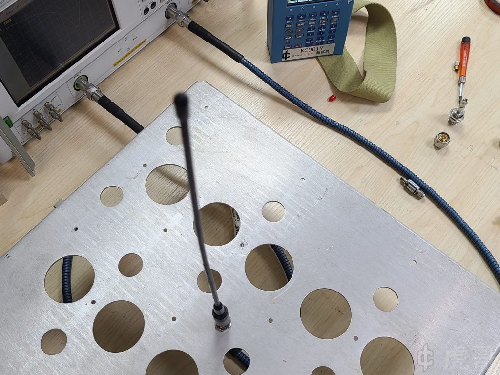
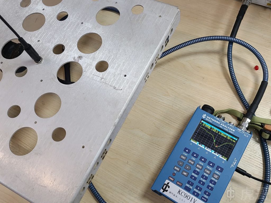
The figure below shows one such modification, where a connector is mounted in the center of the metal plate and a coaxial cable is used to extend the instrument’s port to the center of the plate.
(pic7)
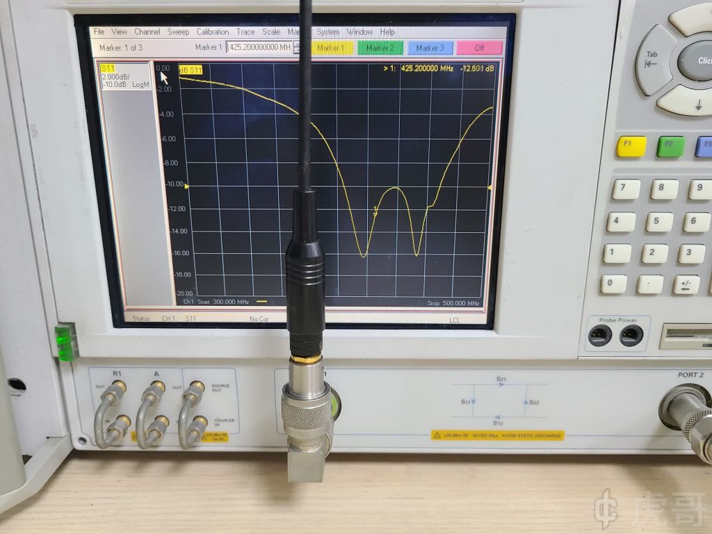
This is the return loss measured by a benchtop instrument
(pic8)
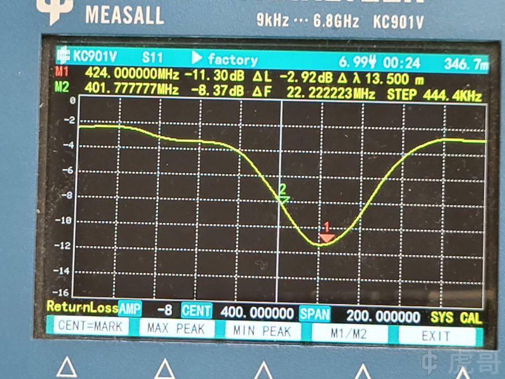
This is the return loss of the same antenna measured by a hand-held instrument.
(pic9)
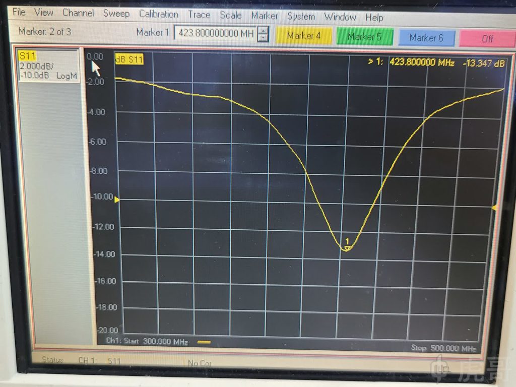
As you can see, the two curves are very close to each other, especially the “resonance” frequency. The reason for the slight difference is simply that the antenna is affected differently by the position of the hand taking the picture.
(pic10)
This video, taken earlier, shows that the antenna is very sensitive to the position of the hand.
(video1)
5, Test the antenna, should try to let the antenna return to the state when used
When testing a handheld radio antenna, you should find the shell of a handheld radio that matches such an antenna, leave the antenna socket in place, replace its circuit board with a coaxial cable, and extend the antenna socket through the cable to the instrument. To minimize interference from the cable, you can have the cable coiled a few times inside the case or run it through a magnetic loop. For slightly larger devices, the antenna analyzer can be mounted inside the case. For testing, have a volunteer, or if available, use an electromagnetic radiation manikin to hold the handheld radio in the usual use position. The antenna performance measured in this way, including but not limited to VSWR, directional maps, etc., is more representative of real usage scenarios. Of course, if there is a convenient means of equivalent testing and simulation can also be used. In conclusion, if the antenna is directly connected to the instrument port, the measured parameters are only of reference significance due to the big difference between the instrument and the actual use conditions. The antenna will have the best effect only if it returns to the real use scenario and optimizes the performance under the real use scenario to the best. From this point of view, a type of handheld radio has to specialize in designing a kind of antenna, which is one of the reasons why some excellent manufacturers of radios have different antennas for each series. Passing VSWR is just a passing grade for the antenna, the real goal is to achieve the best results in the environment in which it is used.

