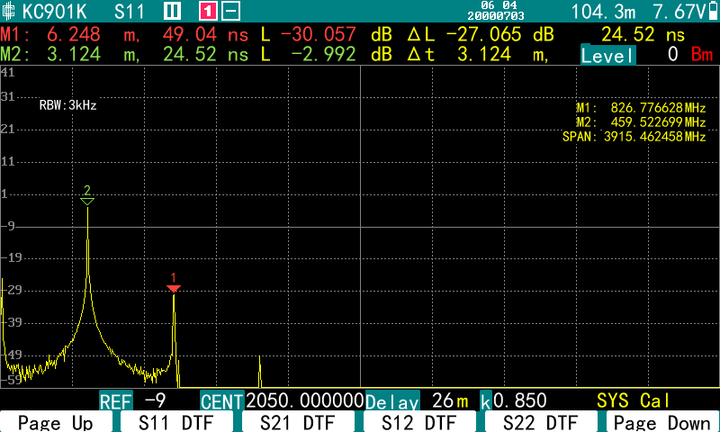
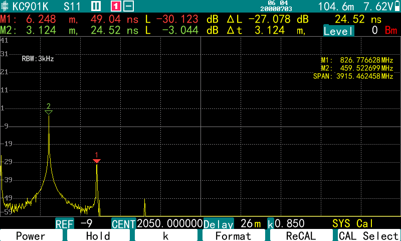
Press the HOME button and you will see the “S11 DTF” option.


The operation is similar to that of the S11, with the format (display mode) option selecting the time-domain SWR or return loss function.

(1) The SPAN button is used to set the range (delay) of the horizontal coordinate. In the soft menu, you can select the unit, if you select “meters” or “kilometers”, the reflection of different distances will be displayed; If “nanoseconds” or “microseconds” is selected, the reflection over time will display. Note that the distance is the one-way distance, half of the signal’s travel; and time is the real time, the signal is a go back and forth twice through the transmission time.

(2) The SCALE key is used to change the vertical coordinate reference.

(3) Only the Center frequency needs to be set in the frequency parameter, the SPAN is set automatically. Sweep width is shown in the upper right corner, along with the frequency corresponding to the marker. The SPAN is related to the distance range. Wider the sweep range, shorter the distance range that can be set. The SWR measured in DTF always corresponds to a certain frequency, you can use marker to read it. Different KC901 models have different minimum ranges that can be set due to the limitations of the frequency range. Higher frequency, shorter the minimum range that can be set. For example, the KC901K can be set to a minimum of 26 m.
When testing some very thick cables (such as the 5-inch air line used in high-power broadcast transmitters), a lower center frequency must be set, such as 500 MHz, otherwise the high end of the sweeping frequency range will exceed the cutoff frequency of the cables and give incorrect results.

(4) K is the velocity coefficient, which is the ratio of the speed of the signal in the cable to the speed of light. Typically for rigid PVC cables, K ≈ 0.67, for cables with foamed dielectrics, K ≈ 0.83, and for air lines commonly used in high power broadcast transmitters, K ≈ 0.95. This parameter can usually be obtained from the cable manufacturer.

(5) If the delay range is set smaller than the actual electrical length of the cable, this may cause aliasing, which is manifested by the appearance of spurious SWR peaks (or smaller return losses). Therefore, please anticipate the electrical length of the cable and always set the range longer than the cable.
