KC901Q is a RF multimeter without built-in directional components. The main reason of the absence of bridge and directional coupler is the fact that there is no elegant solution to balance cost, volume size and performance currently. Taking the solution out of concern and simply integrating forcefully would make KC901Q a tool that is much less appealing to the engineers as a daily partner.
Adopting external bridges and directional couplers could be an ideal solution. Users can choose whichever industrial level products according to their demands of frequency. And the operation would be quite easy.
Considering other models of KC901 series can directly support low frequency down to several kHzs, this tutorial would focus on high-frequency scenario, under which the directional coupler would be the optimal solution. Common models are Agilent 87300B , KRYTAR 104020010 as well as any appropriate Made in China models. They are too affordable to arouse the interest of manufacturer like us to produce them.
While making a choice for directional couplers, its lower limit frequency should not be a major concern. For common directional couplers whose bandwidth is more than 30% of its upper limit frequency, its directionality remains relatively ideal at a frequency that is much lower than its lower frequency limit, while the coupling would drop. Fortunately, KC901Q is designed to have an ideal dynamic range at a low frequency, and as for reflective measurement, the decrease of coupling does not make any difference. Yet, a too-short coupling line would be sensitive to the phase of the reflection, luckily this effect can to some degree be neutralized with calibration model. The instance below would demonstrate the fact that a wide-band directional coupler with a nominal lower frequency limit of 26.5GHz can manage to make it to tens of MHz.
The picture below shows the selected directional coupler for this tutorial, whose nominal frequency range is 26.5-40GHz.
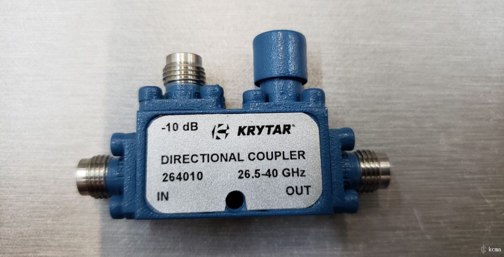
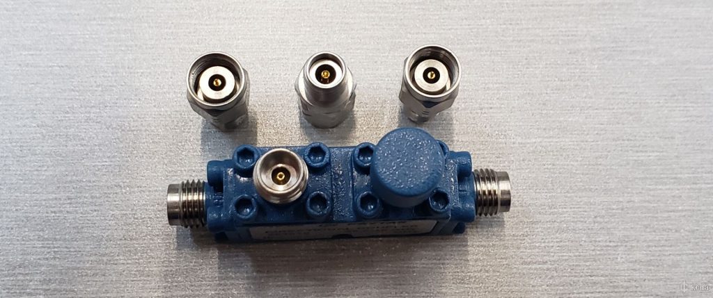
Since this component adopts a 2.4mm connector and it’s not compatible with SMA. So firstly we convert it to 2.92 standard with an adaptor.
Through a 10dB attenuator, connect the output port (port 1) of KC901Q with the directional coupler. Pay attention that a directional coupler normally points out its direction for positive coupling, thus we gonna connect it REVERSELY using its out port as input. The point for using an attenuator is to absorb the reflective wave from the tested object as much as possible, so as to optimize the match of the port.
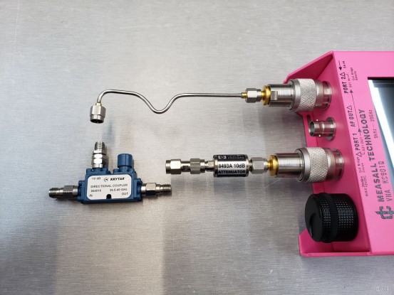
The picture below shows how things look like when they are properly connected. Connect the coupling port of the directional coupler and the input port (port 2) of KC901Q using a semi-steel wire. If a frequency higher than 10GHz is desired, semi-steel wire would be the most affordable yet optimal solution (even better than phase-stable cables). Without it, a slight sway would result in a shift of phase, making the whole experience annoying.
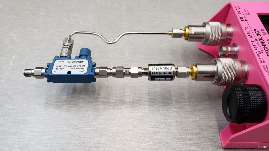
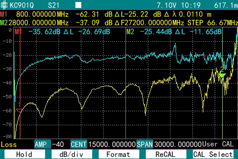
After things are properly connected, time to observe the coupling with S21 function. Measure the curves with/without load at the port and compare them. The more the curve with load drops, the better.
The directional coupler used in this tutorial comes with a coupling of -10dB. Since it’s connected with a attenuator of 10dB in series, the blue curve shown below wanders around -20dB (without load). The yellow curve shows the coupled signal with a load. It’s quite clear that most frequencies come with a directionality better than 20dB. The compromise of directionality above 26Ghz is probably caused by KC901Q’s decrease of dynamic range in that frequency. (After all that’s a 40GHz coupler). Moreover, the load and attenuator used in this article can barely make it to such a high frequency.
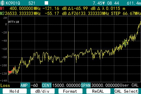
The picture below shows the S21 background noise of KC901Q.
It’s clear that the dynamic range narrows drastically beyond 26Ghz, which accounts for the compromise of directionality in high frequency band shown above.
After checking the directionality of directional coupler, switch to S11 mode and press RECAL button on the soft menu to calibrate the machine.
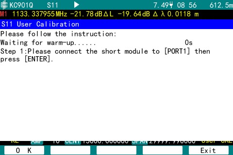
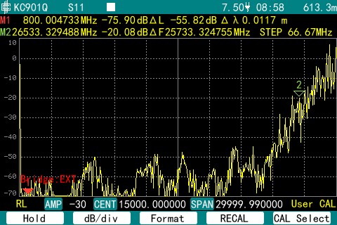
Connect the Short/Opens and load in order according to the notification. The parameters of calibrating components are provided by the manufacturer and need to be input in FUNC-CAL KIT DATA in advance. The S11 background noise, with a load connected, would be displayed after the calibration. It can be seen that apart from zero frequency, the whole band below 24GHz comes with a display range better than 40dB. The actual measuring performance depends on the performance of calibration load.
Connect the Open/Short to the port, and the return loss would be displayed. Like shown below, it fluctuates around 0.
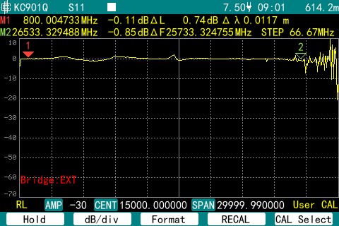
The reason why it’s not strictly zeroed is the production level calibration component is even more expensive than KC901Q. So we choose to DIY one and input the parameter as 0.

Let’s measure the reflection of a 10.5GHz low-pass filter.
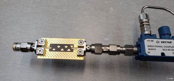
Emmmmm…acceptable…
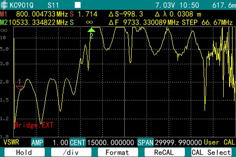
Note that under such a wide span of 30GHz, the distance between each scanning point reaches 66.67MHz, and if it’s used to measure low frequencies, most of the resonance peaks would be missed. Like there is not a single point in the whole short-wave band. Thus for low frequency antenna scenarios the span must be narrowed, both when calibrating and measuring.
The picture below shows a antenna on the Walkie Talkie being measured with a SPAN of 1GHz. The left most part of the screen is the zero frequency and can be used after calibration.
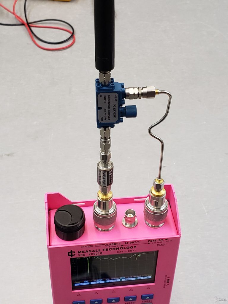
It turns out this antenna comes with a relatively low standing wave near 140MHz.
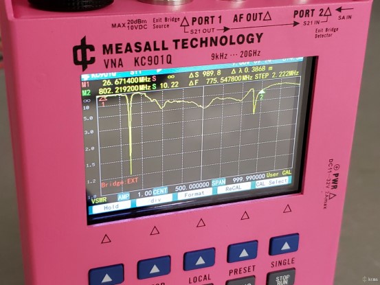
For this kind of unbalanced antennas, the shell of the machine is equivalent to counterpoise, playing a role in antenna radiation. As a consequence, holding the machine with hand or not would result in two totally different measurement output. Users would definitely hold the machine to operate through keyboard at the moment of screenshot, thus the result would be nothing like the curve above, which is measured without touching the machine. The touched version curve is shown below.
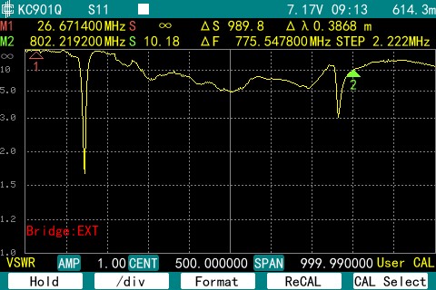
Actually, the directional coupler mentioned above can be used to measure short-wave antennas. However, in dual port Vector Network Analyzer, the forward signal of transmission test is derived from coupling port as well. A unreasonably low coupling level would decrease the dynamic range to nearly zero. What’s more, this unreasonably low coupling level is sensitive to the change of surrounding environment, consequently making it easy to shift. In other words, pairing a dual port VNA with a simple coupler and call it a day would be too good to be true.
Last but not least, the more robust approach is to choose the coupler according to the desired frequency band.
